
Page 127 - Design and Operation of Heat Exchangers and their Networks
P. 127
Steady-state characteristics of heat exchangers 115
For the hot fluid, we use Eq. (3.208) for π <θ<2π and Eq. (3.210)
for 2π <θ<2nπ, and in the outmost region 2nπ <θ<2(n+1/2)π,we
have
_ dt h θ ðÞ
ð
ð
C h + kh r s h Þφ r s h Þ t h θðÞ t c θ 2πð½ Þ ¼ 0 (3.221)
dθ
For the cold fluid, we use Eq. (3.222)
_ dt c θðÞ
ð
ð
C c + kh r + s c Þφ r + s c Þ t h θ +2πð½ Þ t c θðÞ ¼ 0 (3.222)
dθ
for the innermost region 0<θ<π, Eq. (3.209) for π <θ<2(n 1/2)π,
and Eq. (3.211) for 2(n 1/2)π <θ<2nπ.
3.4.2 Effectiveness of spiral heat exchanger and temperature
distribution
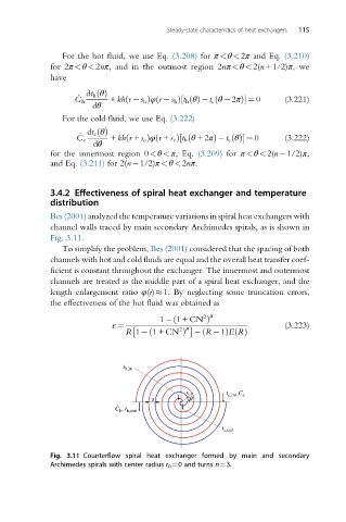
Bes (2001) analyzed the temperature variations in spiral heat exchangers with
channel walls traced by main secondary Archimedes spirals, as is shown in
Fig. 3.11.
To simplify the problem, Bes (2001) considered that the spacing of both
channels with hot and cold fluids are equal and the overall heat transfer coef-
ficient is constant throughout the exchanger. The innermost and outermost
channels are treated as the middle part of a spiral heat exchanger, and the
length enlargement ratio φ(r) 1. By neglecting some truncation errors,
the effectiveness of the hot fluid was obtained as
2 μ
ð
1 1+CN Þ
ε ¼ 2 μ (3.223)
ð
R 1 1+CN Þ R 1ð ÞERðÞ
t h,in
.
r t c,in , C c
. s q
, t
C h h,out
t c,out
Fig. 3.11 Counterflow spiral heat exchanger formed by main and secondary
Archimedes spirals with center radius r 0 ¼0 and turns n¼3.