
Page 131 - Design and Operation of Heat Exchangers and their Networks
P. 131
Steady-state characteristics of heat exchangers 119
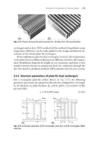
Fig. 3.13 Photos of wavy fins and louvered fins. (A) Wavy fins. (B) Louvered fins.
exchangers such as the ε-NTU method and the method of logarithmic mean
temperature difference can be easily applied to the design and thermal cal-
culation of two-stream plate-fin exchangers.
In the multistream plate-fin heat exchangers, however, the temperatures
of the plates between different fluid pairs are different; therefore, the temper-
ature distributions along the fin height are not symmetric, and there is heat
transfer between streams in nonadjacent layers by conduction through the
fins. The detailed calculation methods will be introduced in the next section.
3.5.2 Structure parameters of plate-fin heat exchangers
For a rectangular plain-fin surface shown in Fig. 3.14, the following
geometric parameters are adopted to describe the configuration: fin height
h f , fin thickness δ f , plate thickness δ p , and fin pitch s f (or number of fins
per inch FPI):
s f ¼ 25:4=FPI mmð Þ (3.237)
s f Plate Plate s f
Fin Fin
d
h f
h f f
d f
d p
(A) (B) d p s ofs
Fig. 3.14 Schematic geometry of (A) rectangular plain fins and (B) rectangular offset
strip fins.