
Page 126 - Design and Operation of Heat Exchangers and their Networks
P. 126
114 Design and operation of heat exchangers and their networks
solution of the correction factor for the logarithmic mean temperature
difference:
2
ln 1 + CN Þ
ð
F 2 (3.216)
CN
where the criterion number CN is defined by
r ffiffiffiffiffiffiffiffi
πA c
CN ¼ 2NTU (3.217)
A
kA
(3.218)
NTU ¼ p ffiffiffiffiffiffiffiffiffiffiffiffi
_ _
C h C c
in which A is the total heat transfer surface area and the cross-sectional area
_
_
A c ¼hs. For n>10 and 0.2 C h =C c 5, Eq. (3.216) agrees very well with
the exact solution developed by Bes and Roetzel (1992b) with an analytical
method for the accurate calculation of the temperature changes in counter-
flow spiral heat exchangers, in which the spiral is composed of circular arc
profiles with the centers of curvature on the angles of an equilateral triangle.
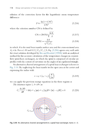
An alternative channel arrangement of a spiral heat exchanger is shown in
Fig. 3.10. By neglecting the heat transfer in the open area at the center and
expressing the radius with
θ
r ¼ r 0 + s h + s c Þ (3.219)
ð
2π
we can apply the previous energy equations in the three regions as
The innermost region 1, 0<θ<π:
_ dt c θðÞ
ð
ð
C c + kh r + s c Þφ r + s c Þ t h θ +2πð½ Þ t c θðÞ ¼ 0 (3.220)
dθ
.
r t , C
t h,in q c,in c
. s r
C h , t h,out 0
t c,out
Fig. 3.10 An alternative channel arrangement in a spiral heat exchanger, turns n¼3.