
Page 132 - Design and Operation of Heat Exchangers and their Networks
P. 132
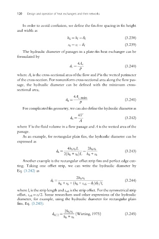
120   Design and operation of heat exchangers and their networks


             In order to avoid confusion, we define the fin-free spacing in fin height
          and width as

                                     h fs ¼ h f  δ f                 (3.238)
                                                                     (3.239)
                                      s fs ¼ s f  δ f
             The hydraulic diameter of passages in a plate-fin heat exchanger can be
          formulated by

                                           4A c
                                       d h ¼                         (3.240)
                                            P
          where A c is the cross-sectional area of the flow and P is the wetted perimeter
          of the cross-section. For nonuniform cross-sectional area along the flow pas-
          sage, the hydraulic diameter can be defined with the minimum cross-
          sectional area,
                                         4A c,min
                                     d h ¼                           (3.241)
                                            P
             For complicated fin geometry, we can also define the hydraulic diameter as
                                           4V
                                       d h ¼                         (3.242)
                                            A
          where V is the fluid volume in a flow passage and A is the wetted area of the
          passage.
             As an example, for rectangular plain fins, the hydraulic diameter can be
          expressed as

                                      4h fs s fs L  2h fs s fs
                               d h ¼          ¼                      (3.243)
                                    2 h fs + s fs ÞL  h fs + s fs
                                     ð
             Another example is the rectangular offset strip fins and perfect edge cut-
          ting. Taking one offset strip, we can write the hydraulic diameter by
          Eq. (3.242) as

                                          2h fs s fs
                            d h ¼                                    (3.244)
                                         ð
                                 h fs + s fs + h fs + s ofs  δ f Þδ f =l s
          where l s is the strip length and s ofs is the strip offset. For the symmetrical strip
          offset, s ofs ¼s f /2. Some researchers used other expressions of the hydraulic
          diameter, for example, using the hydraulic diameter for rectangular plain
          fins, Eq. (3.243):


                                    2h fs s fs
                             d h1ðÞ ¼     ð Wieting, 1975Þ           (3.245)
                                   h fs + s fs