
Page 191 - Design for Six Sigma a Roadmap for Product Development
P. 191
164 Chapter Five
Let us illustrate the concepts in this step through the following
example.
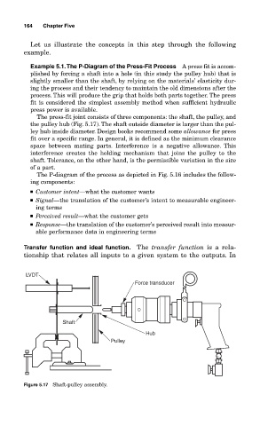
Example 5.1.The P-Diagram of the Press-Fit Process A press fit is accom-
plished by forcing a shaft into a hole (in this study the pulley hub) that is
slightly smaller than the shaft, by relying on the materials’ elasticity dur-
ing the process and their tendency to maintain the old dimensions after the
process. This will produce the grip that holds both parts together. The press
fit is considered the simplest assembly method when sufficient hydraulic
press power is available.
The press-fit joint consists of three components: the shaft, the pulley, and
the pulley hub (Fig. 5.17). The shaft outside diameter is larger than the pul-
ley hub inside diameter. Design books recommend some allowance for press
fit over a specific range. In general, it is defined as the minimum clearance
space between mating parts. Interference is a negative allowance. This
interference creates the holding mechanism that joins the pulley to the
shaft. Tolerance, on the other hand, is the permissible variation in the size
of a part.
The P-diagram of the process as depicted in Fig. 5.16 includes the follow-
ing components:
■ Customer intent—what the customer wants
■ Signal—the translation of the customer’s intent to measurable engineer-
ing terms
■ Perceived result—what the customer gets
■ Response—the translation of the customer’s perceived result into measur-
able performance data in engineering terms
Transfer function and ideal function. The transfer function is a rela-
tionship that relates all inputs to a given system to the outputs. In
LVDT
Force transducer
Shaft
Hub
Pulley
Figure 5.17 Shaft-pulley assembly.