
Page 192 - Design for Six Sigma a Roadmap for Product Development
P. 192
Design for Six Sigma Project Algorithm 165
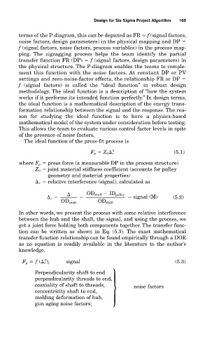
terms of the P-diagram, this can be depicted as FR f (signal factors,
noise factors, design parameters) in the physical mapping and DP
f (signal factors, noise factors, process variables) in the process map-
ping. The zigzagging process helps the team identify the partial
transfer function FR (DP) f (signal factors, design parameters) in
the physical structure. The P-diagram enables the teams to comple-
ment this function with the noise factors. At constant DP or PV
settings and zero-noise-factor effects, the relationship FR or DP
f (signal factors) is called the “ideal function” in robust design
methodology. The ideal function is a description of “how the system
works if it performs its intended function perfectly.” In design terms,
the ideal function is a mathematical description of the energy trans-
formation relationship between the signal and the response. The rea-
son for studying the ideal function is to have a physics-based
mathematical model of the system under consideration before testing.
This allows the team to evaluate various control factor levels in spite
of the presence of noise factors.
The ideal function of the press-fit process is
2
F p Z 0 r (5.1)
where F p press force (a measurable DP in the process structure)
Z 0 joint material stiffness coefficient (accounts for pulley
geometry and material properties)
r relative interference (signal), calculated as
OD shaft ID pulley
r signal (M) (5.2)
OD shaft OD shaft
In other words, we present the process with some relative interference
between the hub and the shaft, the signal, and using the process, we
get a joint force holding both components together. The transfer func-
tion can be written as shown in Eq. (5.3). The exact mathematical
transfer function relationship can be found empirically through a DOE
as no equation is readily available in the literature to the author’s
knowledge.
2
F p f ( r ); signal (5.3)
Perpendicularity shaft to end
perpendicularity threads to end,
coaxiality of shaft to threads, } noise factors
concentricity shaft to end,
molding deformation of hub,
gun aging noise factors;