Page 189 - Design for Six Sigma a Roadmap for Product Development
P. 189

162   Chapter Five


                                                             Uncontrollable Inputs Noises
                                                             Environment  Coupling  Deterioration


                                             Signal (M 1 )
                                             Signal (M 2 )   Level #1 Hierarchy


                                                                      …

                Transfer Functions Level #1                  DP 1  DP 2
                         0   •   0                               Controllable Inputs
                FR 1  A 11          DP 1
                 •    A 21 A 22
                                 •   •
                 •  =  •                                     Uncontrollable Inputs Noises
                             •   0   •
                                                             Environment  Coupling  Deterioration
                FR m  A m1  •  A m(p – 1)  A mm  DP p


                                             Signal (M 1 )
                                             Signal (M 2 )   Level #1 Hierarchy


                 Physical Mapping: Map FRs to                         …
                  Design Parameters (DPs)
                 Functional                                  DP 1  DP 2
                  Domain    Physical                             Controllable Inputs
                            Domain
                   FR               Axiomatic Design  Zigzagging Method  •
                             DP
                   FR 1  FR 2                                 •
                             DP 1  DP 2                       •
                 FR 1.1 FR 1.2
                           DP 1.1  DP 1.2                    Uncontrollable Inputs Noises
                                                             Environment  Coupling  Deterioration

              Transfer Functions Level #k
               FR 1,k  A 11,k  0  •  0  DP 1,k
                •   A 21,k  A 22,k  •  •
                   =                         Signal (M 1 )
                •    •      •    0   •       Signal (M 2 )
               FR m,k  A m1,k  • A m(p – 1) ,k  A mm  DP p,k  Level #1 Hierarchy

                                                                      …

                                                             DP 1  DP 2
                                                                 Controllable Inputs
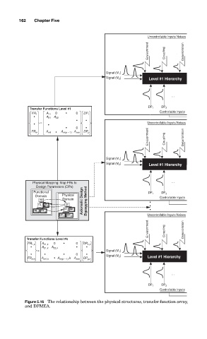
              Figure 5.16 The relationship between the physical structures, transfer function array,
              and DFMEA.
   184   185   186   187   188   189   190   191   192   193   194