
Page 391 - Design for Six Sigma a Roadmap for Product Development
P. 391
Design for X 361
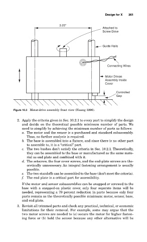
3.25"
Attached to
Screw Drive
Guide Rails
Connecting Wires
Motor Driven
Assembly Inside
Cover
Controlled
Gap
Figure 10.3 Motor-drive assembly front view (Huang 1996).
2. Apply the criteria given in Sec. 10.2.1 to every part to simplify the design
and decide on the theoretical possible minimum number of parts. We
need to simplify by achieving the minimum number of parts as follows:
a. The motor and the sensor is a purchased and standard subassembly.
Thus, no further analysis is required.
b. The base is assembled into a fixture, and since there is no other part
to assemble to, it is a “critical” part.
c. The two bushes don’t satisfy the criteria in Sec. 10.2.1. Theoretically,
they can be assembled to the base or manufactured as the same mate-
rial as end plate and combined with it.
d. The setscrew, the four cover screws, and the end-plate screws are the-
oretically unnecessary. An integral fastening arrangement is usually
possible.
e. The two standoffs can be assembled to the base (don’t meet the criteria).
f. The end plate is a critical part for accessibility.
If the motor and sensor subassemblies can be snapped or screwed to the
base with a snapped-on plastic cover, only four separate items will be
needed, representing a 79 percent reduction in parts because only four
parts remain as the theoretically possible minimum: motor, sensor, base,
and end plate.
3. Revisit all trimmed parts and check any practical, technical, or economic
limitations for their removal. For example, some may argue that the
two motor screws are needed to (a) secure the motor for higher fasten-
ing force or (b) hold the sensor because any other alternative will be