
Page 341 - Design of Reinforced Masonry Structures
P. 341
COLUMNS 5.61
Appropriate Load Combinations should be used when evaluating P for use in Eq. (4.91).
u
When a column is subjected to a lateral seismic load, Seismic Load Combinations 5 and 7 as
specified in ASCE 7-05 Section 12.4.2.3 should be used to calculate P :
u
U = (1.2 + 0.2S )D + rQ + L + 0.2S (5.45, ASCE 7-05 Load Combination 5)
DS
E
U = (0.9 - 0.2S )D + rQ + 1.6H (5.46, ASCE 7-05 Load Combination 7)
E
DS
where S = design, 5 percent damped, spectral response acceleration parameter at
DS
short periods
D = effect of dead load
r = redundancy factor
Q = effect of horizontal seismic forces
E
0.2S D = E , effect of vertical seismic forces
DS
v
The quantity 0.2S D in Eqs. (5.45) and (5.46) is included to account for the effects of
DS
vertical seismic forces.
A discussion on determination of seismic forces based on equivalent lateral force pro-
cedure [including determination of S , the design, 5 percent damped, spectral response
DS
acceleration parameter at short periods used in Eqs. (5.45) and (5.46)] specified in ASCE
7-05 is presented in Chap. 7.
Example 5.12 illustrates calculations for the shear strength of a reinforced CMU column.
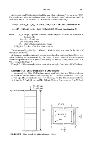
Example 5.12 Shear Strength of a CMU column.
A nominal 16 × 24-in. CMU column having an effective height of 24 ft is reinforced
with four No. 7 Grade 60 bars as shown in Fig. E5.12. The service loads are: D = 20 kips,
L = 20 kips. The seismic lateral load, V = 2 kips, S = 1.25g. The column is reinforced
r
E
DS
with four No. 7 Grade 60 bars and No. 3 Grade 60 ties at 8 in. on center. ′ f = 2000 psi.
m
P D = 20 kips
P Ln = 20 kips
V E = 2 kips
18.825''
24 ft
# 3 @ 8 in.
a.c. 15 5''
8
4#7
5''
23
8
FIGURE E5.12 Shear strength of a reinforced masonry column.