
Page 339 - Design of Reinforced Masonry Structures
P. 339
COLUMNS 5.59
A complete treatment of shear walls is presented in Chap. 7, but because of its concep-
tual and behavioral similarity to columns under combined loading, a discussion of the axial
load and bending moment interaction diagram for shear walls is presented in this section.
Calculations for the interaction diagram for a shear wall are very similar to those pre-
sented in the previous section for columns under combined loading. However, calculations
for the interaction diagram for a shear wall require a few modifications in the calculations
for the interaction diagram for columns presented in the preceding section. This is because
of a few obvious differences between the configurations of a column and a shear wall.
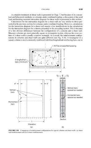
Masonry columns are most generally square or rectangular in plan, whereas the cross sec-
tion of a shear wall is usually a narrow rectangle. As a result, the reinforcement configu-
rations in columns and shear walls are quite different (see Fig. 5.18). A rectangular or a
square column is most commonly reinforced with four longitudinal reinforcing bars, one in
#3 Ties at spacified spacing
4 longitudinal b
bars (minimum)
h
t /2 C L t /2
4" 4"
Vertical bars
Vertical spaced as needed
bars
Horizontal bars
spaced as needed
h
Horizontal
bars
Section
L
Elevation
(a) (b)
FIGURE 5.18 Comparison of reinforcement configurations for typical columns and shear walls. (a) shear
wall reinforcement and (b) Column reinforcement.