
Page 334 - Design of Reinforced Masonry Structures
P. 334
5.54 CHAPTER FIVE
Taking moments of C , C , and T about the centroidal axis of the column, we obtain,
s
m
ha
h
h
d′ +
Td −
M = C s( ) C m( ) ( )
−
−
+
n
2 2 2 2
( 23 625 ) ( 23 625 13 6 ) ( 23 6225 )
.
.
.
.
.
.
.
.
= 65 59 − − 3 8 + 340 − +14 62 19 825 −
2
= 525 54 1704 25 117 14 2 2 2
+
+
.
.
.
= 2346 93k-in. = 1995 6. k-ft
.
φM = 0 9 2346 93) = 2112 2 k-in = 176 k-ft
k
.
.
.(
.
n
Calculations for other points in the interaction diagram are performed on Excel spread-
sheet; so the results obtained are listed in Table E5.11. Calculations for Points 6 and 12
are presented as follows.
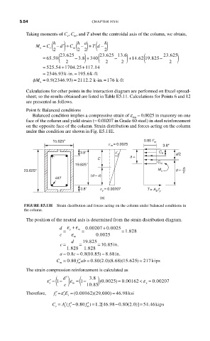
Point 6: Balanced conditions
Balanced condition implies a compressive strain of e = 0.0025 in masonry on one
mu
face of the column and yield strain (= 0.00207 in Grade 60 steel) in steel reinforcement
on the opposite face of the column. Strain distribution and forces acting on the column
under this condition are shown in Fig. E5.11E.
15.625" 0.80 f ʹ m
e m = 0.0025 3.8"
3.8" eʹ s C S a/2
a =
C
C
19.825" m
a
23.625" M n d – 2
(d – c)
4#7
3.8" e y = 0.00207
T = A S f y
(e)
FIGURE E5.11E Strain distribution and forces acting on the column under balanced conditions in
the column.
The position of the neutral axis is determined from the strain distribution diagram.
.
d ε + ε 0 00207 + 0 0025.
= y m = = 1 828.
.
c ε 0 0025
m
.
c = d = 19 825 = 10 85in.
.
.
18. 228 1 828
.
)
c
.
a = 08 = 08 1085 = 8..68in.
.
(
C = . 080 f ab = . 080 ( . )( .868 )(15625 == 217kips
′
20
.
)
m m
The strain compression reinforcement is calculated as
( ) (
.
ε
0 0025)
ε ′ = 1 − ′ d ε = 1 − 38 ) (. = 0 00162. < ε = 0 00207
.
s m y
c 10 85
.
ε
Therefore, f ′= ′E = (.0 00162 )(29 ,000 ) = 46 .98ksi
s s s
C = ′( s f ′ =) 1 . [46 .98 − .80 ( . )] = 54 .46kiips
2
0
A f ′− .0 80
2
0
s
m
s