
Page 332 - Design of Reinforced Masonry Structures
P. 332
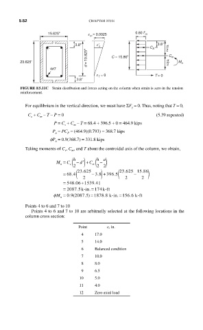
5.52                       CHAPTER FIVE

                    15.625"         e m = 0.0025      0.80 f ʹ m

                              3.8"     eʹ s                    3.8"  s
                                                            C S   2
                                   d = 19.825"  C = 15.86"         C m
         23.625"                                                  s 2  M n
                     4#7
                                       e T = 0                T = 0
                               3.8"
         FIGURE E5.11C  Strain distribution and forces acting on the column when strain is zero in the tension
         reinforcement.

           For equilibrium in the vertical direction, we must have ΣF  = 0. Thus, noting that T = 0,
                                                     y
            C  + C  – T – P = 0                               (5.39 repeated)
             s   m
                      P = C  + C  – T = 68.4 + 396.5 + 0 = 464.9 kips
                          s   m
                      P  = PC  = (464.9)(0.793) = 368.7 kips
                           P
                       n
                     fP  = 0.9(368.7) = 331.8 kips
                       n
           Taking moments of C , C , and T about the centroidal axis of the column, we obtain,
                           s
                             m
                                       ha
                              h
                       M =  C s( )  C m( )
                               −
                                        −
                                d′ +
                         n
                              2        2 2
                               ( 23 625  )     ( 23 625 15 86 )
                                                         .
                                                  .
                                 .
                          = 68 4 .   − 38.  + 39665 .  −
                                  2               2      2
                          =  548 06 1539 41
                                 +
                                      .
                              .
                          =  2087 5 . k--in. = 174 k-ft
                      φM  = 0 9 2087 5 . )  = 1878 8 .  k-in = 1556 6. k-ft
                                               .
                            .(
                         n
           Points 4 to 6 and 7 to 10
             Points 4 to 6 and 7 to 10 are arbitrarily selected at the following locations in the
           column cross section:
                                Point      c, in.
                                  4    17.0
                                  5    14.0
                                  6    Balanced condition
                                  7    10.0
                                  8    8.0
                                  9    6.5
                                 10    5.0
                                 11    4.0
                                 12    Zero axial load