Page 327 - Design of Reinforced Masonry Structures
P. 327

COLUMNS                          5.47

           The strain in compression reinforcement ( ′ ε ) can be calculated similarly from similar
                                          s
           triangles of strain distribution diagram:
                                   ′ ε s  =  cd  ( )
                                      − ′
                                               ′ d
                                             −
                                  ε    c  = 1  c
                                   m
           whence
                                 ( )
                              ε ′ = 1 −  ′ d  ε (compressive         (5.42)
                                                   )
                               s       m
                                     c
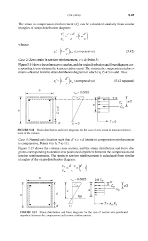
           Case 2: Zero strain in tension reinforcement, c = d (Point 3)
           Figure 5.14 shows the column cross section, and the strain distribution and force diagrams cor-
           responding to zero strain in the tension reinforcement. The strain in the compression reinforce-
           ment is obtained from the strain distribution diagram for which Eq. (5.42) is valid. Thus,
                                 ( )
                                     ′ d
                              ε ′ = 1 −  ε (compressive )     (5.42 repeated)
                               s        m
                                    c
                      b
                                         e m = 0.0025
                                          eʹ s                 dʹ
                                                                      a/2
                                                                 C s
                                                   a              C m
           h                     C = d

                                dʹ      e T  = 0            T = 0

           FIGURE 5.14  Strain distribution and force diagrams for the case of zero strain in tension reinforce-
           ment of the column.
           Case 3: Neutral axis location such that d′ < c < d (strain in compression reinforcement
           is compressive, Points 4 to 6, 7 to 11).
           Figure 5.15 shows the column cross section, and the strain distribution and force dia-
           grams corresponding to neutral axis positioned anywhere between the compression and
           tension reinforcements. The strain in tension reinforcement is calculated from similar
           triangles of the strain distribution diagram:
                                        −
                                  ε   dc   ( )
                                            d
                                     T  =  =  −1
                                  ε m  c    c

                      b                ε m = 0.0025  0.8 fʹ
                                                       m
                                                            dʹ
                                         εʹ s                       a/2
                                                             C s
                                     c           a             C m
                               d
            h
                                           NA
                               dʹ     ε T                T = A S  F S
            FIGURE 5.15  Strain distribution and force diagrams for the case of neutral axis positioned
            anywhere between the compression and tension reinforcements.
   322   323   324   325   326   327   328   329   330   331   332