Page 330 - Design of Reinforced Masonry Structures
P. 330

5.50                       CHAPTER FIVE

           Point 1: Pure axial load, no bending moment
             The axial load capacity can be determined from Eq. (5.12):
                                          ′
                                    φ
                                      .
                                                )
                            φP = 080 080  f A −  A +  f A C
                                 .
                                     [
                                                      ]
                                          (
                              n          m  n   st  y  st  P
           The value of C  for a nominal 16 × 24 in. CMU column with an effective height of 24 ft
                     P
           was determined as 0.793 in Example 5.9 (calculations not repeated here).
             For a nominal 16 × 24 in. CMU column, A  = (15.625)(23.625) = 369.14 in. 2
                                            n
                           φ
                            [
                        .
                   φP = 080 080  f ′( A − A +  f A C P
                             .
                                              ]
                                        )
                                m
                     n
                                       st
                                           y
                                             st
                                   n
                                            −
                                                  +
                                                                 )
                                                            0
                        .
                           (
                                                       2
                                     0
                                   2
                            .
                               0
                      = 080 09))[ .80 ( . )(369 .14 2 .41 ) (60 )( .41 )]( .793)
                      = 417 .6kips
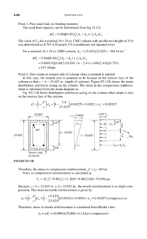
           Point 2: Zero strain on tension side of column when a moment is applied
             In this case, the neutral axis is assumed to be located on the tension face of the
           column so that c = h = 23.625 in. (depth of column). Figure E5.11B shows the strain
           distribution and forces acting on the column. The strain in the compression reinforce-
           ment is calculated from the strain diagram as:
             Fig. E5.11B Strain distribution and forces acting on the column when strain is zero
           on the tension face of the column.
                     ( ) (
                                                      ε
                                                     >
                  ε
                   ′ = 1 −  ′ d  ε  = 1 −  38 .  ) (.  = 0 0021 ε = 0 00207
                                                           .
                                                .
                                        0 0025)
                   s       m                           y
                                   .
                        c        23 625
                   15.625"             e m = 0.0025    0.55 f ʹ m
                              3.8"        eʹ s                 3.8"  s
                                                            C S
                                                                   2
                    4#7
                                 d = 19.825"                        C m
         23.625"                             c = 23.625"           s
                                                                   2   M n
                                           e T                C S = A S F S
                               3.8"
                Tension side
                of column
         FIGURE E5.11B
           Therefore, the stress in compression reinforcement,  ′ f  = f  = 60 ksi
                                                    y
                                                 s

             Force in compression reinforcement is calculated as
                     C = ′(      f ′ =) 1 . [60 − .80 ( . )] = 70 .08kips
                                                2
                                                 0
                                       2
                        A f ′− .0 80
                                           0
                      s  s  s     m
           Because c = h = 23.625 in. > d = 19.825 in., the tensile reinforcement is in slight com-
           pression. The strain in tensile reinforcement is given by
             T ( ) (       19 825 )
                             .
                   d
                                               <
                                  0 0025)
                                                                     )
                                                     .
                                           .
              ε = 1 −  ε = 1 −   (.     = 0 0004 < ε  = 0 00207(compressive
                   c  m    23 625                 y
                             .
           Therefore, stress in tensile reinforcement is calculated from Hooke’s law:
                      f  = e E  = (0.0004)(29,000) =11.6 ksi (compressive)
                      T
                          T s
   325   326   327   328   329   330   331   332   333   334   335