
Page 333 - Design of Reinforced Masonry Structures
P. 333
COLUMNS 5.53
15.625" e m = 0.0025 0.80 f ʹ m
3.8" eʹ s 3.8"
7.8"
C S
17" a = 13.6" C m
23.625" M n
4#7 NA
2.825"
T = A S F S
3.8" e T
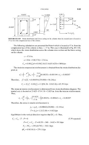
FIGURE E5.11D Strain distribution and forces acting on the column when the neutral axis is located at
17 in. from the compression face of the column.
The following calculations are presented for Point 4 which is located at 17 in. from the
compression face of the column so that c = 17 in. This case is illustrated in Fig. E5.11D,
which shows the strain distribution across the column cross section and the forces acting
on the column.
c = 17.0 in.
a = 0.8c = 0.8(17.0) = 13.6 in.
′
C = 0 80. f ab = 0 80 2 0 13 6 15 625. ( . )( . )( . ) = 340kips
m
m
The strain in compression reinforcement is obtained from the strain distribution dia-
gram as
( ) (
ε
.
0 0025)
′ = 1 − ′ d ε = 1 − 38 . ) (. = 0 00194 < ε = 0 00207
.
s m y y
c 17 0 .
ε
Therefore, f ′= ′E = (.0 00194 )(29 ,000 ) = 56 .26ksi
s s s
=
A f ′− .080
C = ′( f ′ =) 12 . − . ( . )] 6559 kiips
.
0820
. [5626
s s s m
The strain in tension reinforcement is determined from strain distribution diagram. The
neutral axis is located at 23.625–17.0–3.8 = 2.825 in. from the tension reinforcement.
Thus,
T ( ) ( 19 825 )
d
.
ε = −1 ε = −1 0 0025) = 0 00042 ε = 0 00207
ε
<
.
.
(.
.
c m 17 0 y
Therefore, the stress in tensile reinforcement is
f = e E = (0.00042)(29,000) = 12.18 ksi
T T s
T = A f = 1.2(12.18) = 14.62 kips
s T
Equilibrium in the vertical direction requires that ΣF = 0. Thus,
y
C + C – T – P = 0 (5.39 repeated)
m
s
P = C + C – T = 65.59 + 340 – 14.62 = 391 kips
s
m
P = PC = (391)(0.793) = 310.1 kips
P
n
fP = 0.9(310.1) = 279.1 kips
n