
Page 329 - Design of Reinforced Masonry Structures
P. 329
COLUMNS 5.49
In all cases, the stresses in the reinforcement, in compression or tension, are calculated
from Hooke’s law ( f = eE), but are limited to a maximum of the yield strength of the rein-
forcement. These stresses are then used to calculate forces in the reinforcements.
Example 5.11 presents calculations for axial load-bending moment interaction diagram
for masonry columns. Example 5.11 uses the following two notations which are slightly
different from those used earlier:
h ′ = effective height of a column (= h in previous examples)
h = nominal width of a column cross section (larger cross-sectional dimension, overall
depth of a beam section)
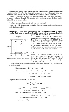
Example 5.11 Axial load-bending moment interaction diagram for a rect-
angular CMU column bending about its major axis of cross section (axis
parallel to the short side).
15.625" A nominal 16 × 24 in. CMU column having
an effective height of 24 ft is reinforced with four
3.8" No. 7 Grade 60 bars as shown in Fig. E5.11A, placed
at 3.8 in. from the face of the column. Assuming
4#7 m ′ f = 2000 psi, plot the axial load-bending moment
interaction diagram for this column. The bending
23.625" of the column occurs about its major axis (axis par-
allel to the short side of the cross section).
3.8" Solution
3.8" 3.8" Given: CMU column nominal 16 × 24 in.,
b = 15.625 in., h = 23.625 in., d = 19.825 in., d ′=
2
2
FIGURE E5.11A Column cross section. 3.8 in., A = 2.41 in. (four No. 7 bars), ′ A = 1.2 in.
st
s
(two No. 7 bars), column height h′ = 24 ft, ′ f =
m
2000 psi, f = 60 ksi.
y
Check code compliance with respect to dimensional limits, h ′/t ratio and longitudi-
nal reinforcement.
Nominal column width = 16 > 8 in. OK
Nominal column depth = 24 in. < 3t = 3(16) = 48 in. OK
h ′/t = (24)(12)/16 = 18 < 30 OK
A = (15.625)(23.625) = 369.14 in. 2
n
Longitudinal reinforcement, A = 2.41 in. 2
st
.
ρ = A st = 241 = 0 0065.
.
A 369 0
n
r max = 0.04 r min = 0.0025 r provided = 0.0065
0.0025 < 0.0065 < 0.04 OK
Lateral ties: Tie diameter = 0.375 > 0.25 in. OK
s = 8 in. ≤ 16d = 16 (7/8) = 14 in. OK
b
≤ 48 tie diameter = 48(0.375) = 18 in. OK
≤ 16 in. OK