
Page 328 - Design of Reinforced Masonry Structures
P. 328
5.48 CHAPTER FIVE
whence
T ( )
d
ε = −1 ε (tensile ) (5.43)
c m
Similar, the strain in the compression reinforcement is calculated as
′ ε cd ( )
− ′
′ d
s = = 1 −
ε c c
m
whence
( )
′ d
ε ′ = 1 − ε (compressive ) (5.42 repeated)
s m
c
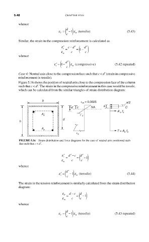
Case 4: Neutral axis close to the compression face such that c < d′ (strain in compressive
reinforcement is tensile).
Figure 5.16 shows the position of neutral axis close to the compression face of the column
such that c < d ′. The strain in the compressive reinforcement in this case would be tensile,
which can be calculated from the similar triangles of strain distribution diagram:
b ε m = 0.0025 a/2
dʹ c NA a C
Aʹ s f s
A s ʹ εʹ s
d
h
A s
T = A s f s
ε s
FIGURE 5.16 Strain distribution and force diagrams for the case of neutral axis positioned such
that such that c < d′.
′ ε d ′ − c ( )
′ d
s = = −1
ε c c
m
whence
′ d
ε ′ = ( ) m ) (5.44)
− ε (tensile
1
s
c
The strain in the tension reinforcement is similarly calculated from the strain distribution
diagram:
−
ε dc ( )
d
T = = −1
ε m c c
whence
T ( )
d
)
ε = −1 ε (tensile (5.43 repeated)
c m