
Page 368 - Design of Reinforced Masonry Structures
P. 368
WALLS UNDER GRAVITY AND TRANSVERSE LOADS 6.19
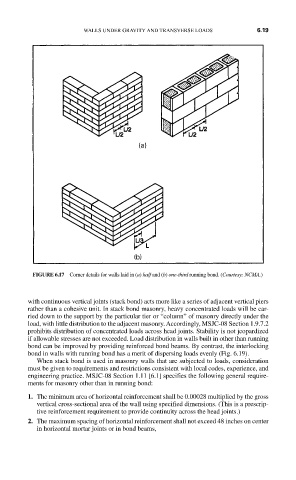
FIGURE 6.17 Corner details for walls laid in (a) half and (b) one-third running bond. (Courtesy: NCMA.)
with continuous vertical joints (stack bond) acts more like a series of adjacent vertical piers
rather than a cohesive unit. In stack bond masonry, heavy concentrated loads will be car-
ried down to the support by the particular tier or “column” of masonry directly under the
load, with little distribution to the adjacent masonry. Accordingly, MSJC-08 Section 1.9.7.2
prohibits distribution of concentrated loads across head joints. Stability is not jeopardized
if allowable stresses are not exceeded. Load distribution in walls built in other than running
bond can be improved by providing reinforced bond beams. By contrast, the interlocking
bond in walls with running bond has a merit of dispersing loads evenly (Fig. 6.19).
When stack bond is used in masonry walls that are subjected to loads, consideration
must be given to requirements and restrictions consistent with local codes, experience, and
engineering practice. MSJC-08 Section 1.11 [6.1] specifies the following general require-
ments for masonry other than in running bond:
1. The minimum area of horizontal reinforcement shall be 0.00028 multiplied by the gross
vertical cross-sectional area of the wall using specified dimensions. (This is a prescrip-
tive reinforcement requirement to provide continuity across the head joints.)
2. The maximum spacing of horizontal reinforcement shall not exceed 48 inches on center
in horizontal mortar joints or in bond beams,