
Page 367 - Design of Reinforced Masonry Structures
P. 367
6.18 CHAPTER SIX
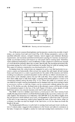
FIGURE 6.16 Running and stack bond patterns.
Two of the most common bond patterns used in masonry construction, in order of pref-
erence, are running bond and stack bond (Fig. 6.16). Design parameters, such as code-
specified allowable stresses, strength formulas, lateral support and minimum thickness
requirements, and maximum permitted reinforcement spacing for masonry are based pri-
marily on structural testing and research on wall panels laid in running bond. Therefore,
when a different bond pattern is used, its influence on the compressive and flexural strength
of a wall should be properly taken into account. Specifically, the maximum permitted rein-
forcement spacing for walls in stack bond may be smaller than for walls in running bond.
This aspect of masonry construction was discussed earlier in Chap. 2.
In running bond, the vertical joints are staggered in such a way that head joints in suc-
cessive courses are horizontally offset at least one-quarter the unit length. In half running
bond, each head joint in a course is positioned over the center of the masonry unit below,
resulting in an attractive symmetrical pattern on the wall face in which vertical joints (i.e.,
head joints) in the alternate courses line up with each other. Since typical masonry units
have their width equal to half their length, a running-bond pattern permits a corner to be
constructed without cutting the units (Fig. 6.17a). When the width of a masonry unit is
one-third of its length, running bond pattern can be obtained with one-third overlap of units
in successive courses, so that the corners can be constructed without cutting the units
(Fig. 6.17b). In this case also, the head joints in the alternate courses will line up resulting
in a symmetrical pattern in the face of the wall. Figure 6.18 shows corner details of walls
built from various size concrete masonry units laid in half running bond.
The MSJC Code [6.1] defines stack bond as a bond pattern other than running bond;
usually the placement of units is such that the head joints in the successive courses are verti-
cally aligned. This definition is in conformity with 2009 IBC [6.2], but differs slightly from
the past practices which defined stack bond, a bond pattern in which less than 75 percent
of the units in any transverse vertical plane lapped the ends of the units below either (a)
a distance less than one-half the height of the unit below, or (b) less than one-fourth the
length of the unit.
The fundamental difference in walls built in running bond and stack bond is in the pat-
tern of vertical joints: staggered (discontinuous) in the former and (almost) continuous in
the latter. Compressive strength is similar for stack and running bond construction. A wall