
Page 370 - Design of Reinforced Masonry Structures
P. 370
WALLS UNDER GRAVITY AND TRANSVERSE LOADS 6.21
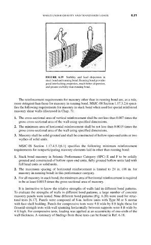
FIGURE 6.19 Stability and load dispersion in
stack bond and running bond. Running bond provides
good interlocking properties, much better dispersion,
and greater stability than running bond.
The reinforcement requirements for masonry other than in running bond are, as a rule,
more stringent than those for masonry in running bond. MSJC-08 Section 1.17.3.2.6 speci-
fies the following requirements for masonry in stack bond when used for special reinforced
masonry shear walls (discussed in Chap. 7):
1. The cross-sectional area of vertical reinforcement shall be not less than 0.007 times the
gross cross-sectional area of the wall using specified dimensions.
2. The minimum area of horizontal reinforcement shall be not less than 0.0015 times the
gross cross-sectional area of the wall using specified dimensions.
3. Masonry shall be solid grouted and shall be constructed of hollow open-end units or two
wythes of solid units.
MSJC-08 Section 1.17.4.5.1[6.1] specifies the following minimum reinforcement
requirements for nonparticipating masonry elements laid in other than running bond:
1. Stack bond masonry in Seismic Performance Category (SPC) E and F to be solidly
grouted and constructed of hollow open-end units, fully grouted hollow units laid with
full head units or solid units.
2. The maximum spacing of horizontal reinforcement is limited to 24 in. (48 in. for
masonry in running bond) in this performance category.
3. For all masonry in stack bond, the minimum area of horizontal reinforcement is required
to be at least 0.0015 times the gross sectional area of masonry.
It is instructive to know the relative strengths of walls laid in different bond patterns.
To evaluate the strengths of walls in different bond patterns, a large number of concrete
masonry panels were tested. Nine different bond patterns (Fig. 6.20) were used for struc-
tural tests [6.17]. Panels were composed of 8-in. hollow units with Type M or S mortar
with face shell bedding. Panels for compressive tests were 4 ft wide by 8 ft high; those for
flexural strength tests with wall spanning horizontally between supports were 8 ft wide by
4 ft high. For compressive tests, loading was applied at an eccentricity of one-sixth of the
wall thickness. A summary of findings from these tests can be found in Ref. 6.18.