
Page 429 - Design of Reinforced Masonry Structures
P. 429
WALLS UNDER AXIAL AND TRANSVERSE LOADS 6.79
In Eq. (6.7), F is not required to be greater than
p
F = 1.6S I W (6.8 repeated)
p DS p p
or less than I given by Eq. (6.9):
p
F = 0.3S I W (6.9 repeated)
p DS p p
When fence walls are designed as unbraced cantilever walls, the values of z and h in
Eq. (6.7) should be taken equal to the height of the wall so that z/h = 1. The value of coeffi-
cients a and R should be taken, respectively, as 2.5 and 2.5 so that the resulting equation is
p
p
04 aS ⎛ z ⎞
.
F = p DS ⎜ 12 ⎟ W
+
p ⎛ R ⎞ ⎝ h ⎠ p
⎜ ⎝ p I ⎠ ⎟
p
h⎞
.(
+
= 04 25.)S S DS ⎛ ⎜ 12 ⎟ W
.
25 ⎝ h ⎠ p
I p
= 12 SI W (6.28)
.
DS p p
Since the value of F given by Eq. (6.28) is smaller than that given by Eq. (6.8), but
p
larger than that given by Eq. (6.9), Eq. (6.28) will govern for seismic lateral load. Note that
for cantilever conditions, the maximum moment and shear occur at the base of the wall.
Alternatively, fence walls can be designed as panels supported by pilasters (discussed in
Section 6.9.2).
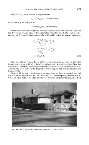
Figure 6.44 shows a typical concrete masonry fence wall in a residential area and
Fig. 6.45 shows details for a CMU for a fence wall. It is common practice to use 6 or 8 in.
CMU for fence walls; 4-in. CMU may be used for walls of smaller heights, say 4 ft or
FIGURE 6.44 A typical fence wall in a residential area. (Courtesy: Author.)