
Page 527 - Design of Reinforced Masonry Structures
P. 527
SHEAR WALLS 7.89
3. Determine seismic design category.
(a) Daycare facility: Occupancy Category III, based on S = 1.17 > 0.5, S is D
DC
DS
Based on S = 0.7 > 0.2, SDC is D.
D1
But S = 0.81 > 0.75; therefore, for this Occupancy Category III building,
1
SDC is E.
(b) Police station: Occupancy Category IV, based on S = 1.17 > 0.5, S is D
DC
DS
Based on S = 0.7 > 0.2, SDC is D.
D1
But S = 0.81 > 0.75; therefore, for this Occupancy Category IV building,
1
SDC is F.
7.10.3 Design for Flexure
A shear wall is necessarily subjected to forces in two perpendicular planes. It receives lat-
eral loads perpendicular to wall (the out-of-plane lateral loads) that cause the wall to bend
out-of-plane, a topic discussed in Chap. 6. Additionally, it receives in-plane lateral loads
which it resists as a shear wall. Procedure for designing a wall as a shear wall is discussed
in this section. Although these two sets of forces are not assumed to act concurrently, the
wall must be adequate to resist these two sets of forces independently.
A shear wall is analyzed as a vertical beam. Under the action of in-plane lateral force
acting on the wall, the wall is subjected to shear as well as moment. For a single-story wall,
the magnitude of this moment equals the lateral force times the wall height. In addition, the
wall is subjected to a seismic lateral force at the midheight due to its own inertia. This inertial
force equals the seismic coefficient times the self-weight of the wall, and the moment due
to this lateral force equals this force times the distance from the center of gravity of mass of
the wall to the base. In a single-story building, this moment is added to the moment caused
by the in-plane lateral force applied at the top of wall. See Example 7.16. In multistory shear
walls, the self-weight of walls is lumped the with the masses tributary at various floor levels.
The shear wall is subjected to in-plane lateral force at each diaphragm level as well as inertial
forces due to the self-weight of shear walls themselves, which act at the centers of gravity of
their tributary masses. The wall must be designed for all forces that it must resist.
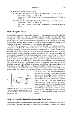
The total moment on the wall is resisted by the rectangular section of the wall (as seen
in plan). Often, it is easier to visualize the wall as a cantilever beam by simply rotating the
o
wall by 90 (Fig. 7.34). Moment causes flex-
h ural stresses which are tensile and compres-
sive, and vary linearly between the two vertical
P
ends of the wall. In addition, the wall may be
∆ C subjected to axial loads in addition of the self-
d
weight of the wall. Axial loads on the wall,
when concentric, cause uniform compressive
stresses over the wall cross section. Depending
on the magnitude of the moment, the section of
P
the wall may be uncracked or cracked. This is
FIGURE 7.34 Visualization of shear wall as
a cantilever. Tension and compression on the determined by comparing the axial compres-
ends of the wall will reverse upon the reversal sive stress with the flexural tensile stress in the
of the applied load. masonry.
7.10.4 Minimum Thickness Requirements for Shear Walls
There are no specific code requirements for minimum thickness of shear walls, but 6 in. is
considered as a practical minimum to satisfy grouting requirements. In bearing wall systems,