
Page 530 - Design of Reinforced Masonry Structures
P. 530
7.92 CHAPTER SEVEN
In Eq. (7.82), the value of M /V d must be positive and need not be taken greater
u
u
than 1.0.
(d) The nominal shear strength provided by steel reinforcement is calculated from
Eq. (7.83):
⎛ A ⎞
V = 05. v fd (7.83)
s ⎝ s ⎠ y v
In the above equations d = L = length of wall for all practical purposes and P =
v w u
axial force associated with V
u
7.10.6 Other Reinforcement Requirements for Shear Walls
Various types of masonry shear walls were discussed in Section 7.10.1. All walls should
be reinforced as required by design. However, it is reiterated that, with the exception of
unreinforced masonry shear walls, MSJC-08 specifies minimum amount of reinforcement
and detailing requirements (both are mandatory, see Figs. 7.31 through 7.33) for detailed
plain reinforced masonry walls and ordinary reinforced masonry shear walls, intermediate
reinforced masonry shear walls, and special reinforced masonry shear walls.
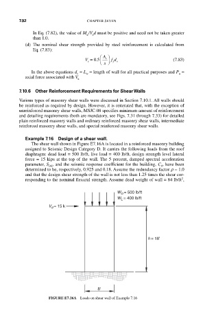
Example 7.16 Design of a shear wall.
The shear wall shown in Figure E7.16A is located in a reinforced masonry building
assigned to Seismic Design Category D. It carries the following loads from the roof
diaphragm: dead load = 500 lb/ft, live load = 400 lb/ft, design strength level lateral
force = 15 kips at the top of the wall. The 5 percent, damped spectral acceleration
parameter, S , and the seismic response coefficient for the building, C , have been
DS
S
determined to be, respectively, 0.925 and 0.18. Assume the redundancy factor r = 1.0
and that the design shear strength of the wall is not less than 1.25 times the shear cor-
2
responding to the nominal flexural strength. Assume dead weight of wall = 84 lb/ft ,
W D = 500 lb/ft
W L = 400 lb/ft
V = 15 k
d
h = 18'
8'
FIGURE E7.16A Loads on shear wall of Example 7.16