
Page 528 - Design of Reinforced Masonry Structures
P. 528
7.90 CHAPTER SEVEN
load-bearing walls might also be acting as shear walls. Typical wall thickness would be 8-
in. nominal. Larger thickness might be required for tall structures. A discussion on available
thicknesses of masonry hollow units is presented in Chap. 3. It might be preferable and
economical to use higher-strength masonry rather than larger size units, which would be
heavier and require more space to build. Nominal 8-in. walls have been used for examples
in this chapter.
7.10.5 Design Shear Strength
The shear strength of shear walls can be determined in a manner similar to that used for
beams, columns, and piers (see examples in Chaps. 4 and 5). However, to minimize the pos-
sibility of brittle failure of shear walls in structures built in high seismic regions, the design
strength of such shear walls is determined a bit differently. The procedure of determining
the nominal shear strength of such shear walls is specified in MSJC-08 Section 3.3.6, and
explained in MSJC-08 Commentary Section 3.3.6.5.3. The model presented in the follow-
ing discussion is based on 2006 IBC Section 2106.5.2. The strength reduction factor, f, to
be used in conjunction with nominal shear strength is 0.8 (MSJC-08 Section 3.1.4.3).
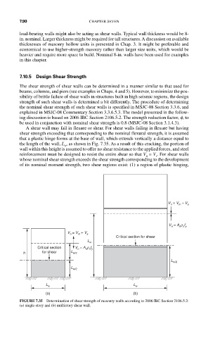
A shear wall may fail in flexure or shear. For shear walls failing in flexure but having
shear strength exceeding that corresponding to the nominal flexural strength, it is assumed
that a plastic hinge forms at the base of wall, which extends vertically a distance equal to
the length of the wall, L , as shown in Fig. 7.35. As a result of this cracking, the portion of
w
wall within this height is assumed to offer no shear resistance to the applied forces, and steel
reinforcement must be designed to resist the entire shear so that V = V . For shear walls
s
n
whose nominal shear strength exceeds the shear strength corresponding to the development
of its nominal moment strength, two shear regions exist: (1) a region of plastic hinging,
V n = V m + V s
V n = A n r n f y
V n = V m + V s
Critical section for shear
L w
Critical section V n = A n r n f y
h for shear L w/2
L w/2
L w/2
L w L w
(a) (b)
FIGURE 7.35 Determination of shear strength of masonry walls according to 2006 IBC Section 2106.5.2:
(a) single-story and (b) multistory shear wall.