
Page 533 - Design of Reinforced Masonry Structures
P. 533
SHEAR WALLS 7.95
Provide only minimum horizontal reinforcement
A v,min = 0.0007Ag
2
= 0.0007 (7.625)(12) = 0.064 in. /ft
Provide No. 3 bars at 16 in. on centers vertically
1
2
1
01
A = (. )( ) = . 0 0825 in /ft > 0.064 in. satisfactory
2
2
v
16
Requirements for maximum permissible spacing are the same as determined earlier
for the plastic hinge segment of the wall.
s max = 48 in.
s provided = 16 in. < 48 in. satisfactory
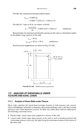
Reinforcement requirements are shown in Fig. E7.16B.
≤ 8 in.
≤16 in.
#3 @ 16" o.c.
Hoz. & Vert.
h = 18'
L w = 8'
FIGURE E7.16B Reinforcement requirements.
7.11 ANALYSIS OF SHEAR WALLS UNDER
FLEXURE AND AXIAL LOADS
7.11.1 Analysis of Shear Walls under Flexure
Shear walls constitute the lateral load–resisting elements in both masonry and concrete
shear wall buildings (referred to as bearing wall systems in design codes), and dual systems
and shear wall–frame interactive systems. By their very nature shear walls are subjected to
the following concurrent forces:
1. Gravity loads, which cause axial compressive stresses in the wall.
2. Lateral loads, which cause shear stresses in the wall as well as bending moment and
overturning moment in the wall, the latter being the maximum moment at the bottom of
the shear wall.