
Page 537 - Design of Reinforced Masonry Structures
P. 537
SHEAR WALLS 7.99
1. Factored axial load stress ≤ 0.2 ′ f
m
2. Slenderness ratio (h/t ratio) ≤30
3. Minimum nominal thickness ≥6 in. (Not a code requirement, but a practical minimum.)
It is, therefore, only logical that a limit to h/t = 30 be maintained for shear walls.
Expressions for axial loads on compression elements were derived in Chap. 5. It was shown
that for rectangular sections,
r = t (5.16 repeated)
12
so that t = r 12 (7.96)
Therefore, the condition h/t = 30 can be expressed in terms of h/r ratio as follows:
h h
= = 30
t r 12
h
so that = 30 12 = 103 923 (7.97)
.
r
Equation (7.97) can be treated as the upper limit for h/r ratio for a shear wall. Accordingly,
the nominal axial strength of a shear wall can be expressed, based on MSCJC-08 Section
3.3.4.1, Eq. (3.17) [see Chap. 5, Eq. (5.11)]:
P = 080 080 f ′( A − A + f A ⎜ ] ⎛ 70 r ⎞ ⎟ 2
.[ .
)
n m n s y s ⎝ h ⎠
⎛ 70 ⎞ 2
= 08 . 000 80[. ( ′ f A − A ) + f A ] ⎜ ⎟
m n s y s ⎝ 103 923 ⎠
.
= 03 . 663 0 80[. ( ′ f A − A ) + f A ] (7.98)
m n s y s
Equation (7.98) can be treated as the limiting value of nominal axial capacity of reinforced
masonry walls.
The strength factor f to be used for axial loads, axial loads with flexure, or flexure, is 0.9
(MSJC-08 Section 3.1.4.1). Example 7.17 presents analysis of a shear wall under flexure.
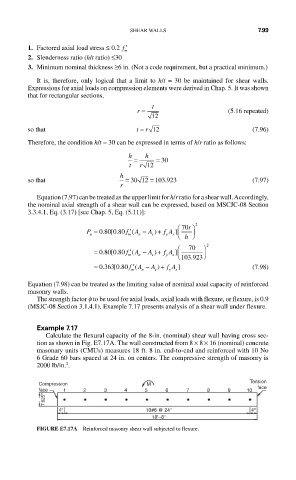
Example 7.17
Calculate the flexural capacity of the 8-in. (nominal) shear wall having cross sec-
tion as shown in Fig. E7.17A. The wall constructed from 8 × 8 × 16 (nominal) concrete
masonary units (CMUs) measures 18 ft. 8 in. end-to-end and reinforced with 10 No
6 Grade 60 bars spaced at 24 in. on centers. The compressive strength of masonry is
2
2000 lb/in. .
Tension
Compression M
face 1 2 3 4 5 6 7 8 9 10 face
7.625''
4'' 10#6 @ 24'' 4''
18'–8''
FIGURE E7.17A Reinforced masonry shear wall subjected to flexure.