
Page 541 - Design of Reinforced Masonry Structures
P. 541
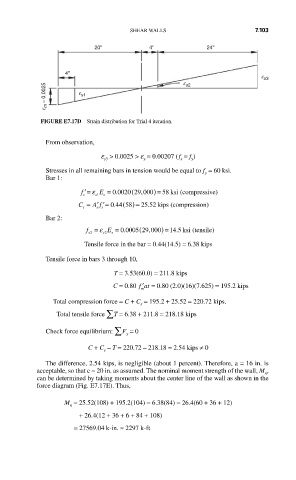
SHEAR WALLS                       7.103

                          20''           4''             24''


                   4''
                                                                       e s3
             e m = 0.0025  e s1
                                                  e s2


            FIGURE E7.17D  Strain distribution for Trial 4 iteration.

             From observation,
                            e  > 0.0025 > e  = 0.00207 ( f  = f )
                             s3
                                                    y
                                                  s
                                        y
             Stresses in all remaining bars in tension would be equal to f  = 60 ksi.
                                                        y
             Bar 1:
                       f s ′= ε s1 E s  = 0 0020.  (29 000 ) = 58 ksi (compressive)
                                       ,
                                    8
                          A f
                                         .
                                   5
                      C = ′′= 044.  ( ) = 2552 kips (compression)
                       s
                           s s
             Bar 2:
                                      (
                         f = ε s2 E =  0 0005 29 000) = 14 5 ksi (tensile)
                                         ,
                                  .
                                                .
                         s2
                               s
                        Tensile force in the bar = 0.44(14.5) = 6.38 kips
             Tensile force in bars 3 through 10,
                                T = 3.53(60.0) = 211.8 kips
                               C = 0.80  ′ fat = 0.80 (2.0)(16)(7.625) = 195.2 kips
                                       m
               Total compression force = C + C  = 195.2 + 25.52 = 220.72 kips.
                                       s
                Total tensile force ∑ T = 6.38 + 211.8 = 218.18 kips
             Check force equilibrium: ∑ F  = 0
                                   y
                           C + C  – T = 220.72 – 218.18 = 2.54 kips ≠ 0
                             s
             The difference, 2.54 kips, is negligible (about 1 percent). Therefore, a = 16 in. is
           acceptable, so that c = 20 in. as assumed. The nominal moment strength of the wall, M ,
                                                                        n
           can be determined by taking moments about the center line of the wall as shown in the
           force diagram (Fig. E7.17E). Thus,
                  M  = 25.52(108) + 195.2(104) − 6.38(84) − 26.4(60 + 36 + 12)
                    n
                      + 26.4(12 + 36 + 6 + 84 + 108)
                     = 27569.04 k-in. ≈ 2297 k-ft