Page 542 - Design of Reinforced Masonry Structures
P. 542

7.104                     CHAPTER SEVEN

                                        C
                        108''            L            108''
         4''
             C  6.38K
          C s                                                            26.4 kips
           8'' 28''  24''  24''  24''  12'' 12''  24''  24''  24''  24''
                                                                       4''
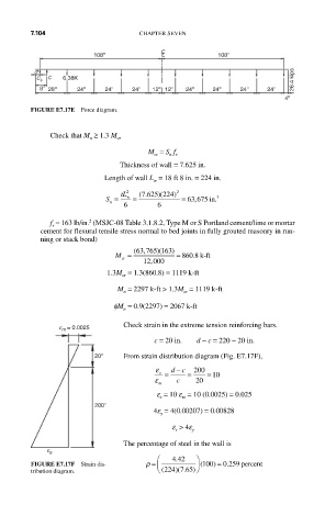
         FIGURE E7.17E  Force diagram.


             Check that M ≥ 1.3 M
                       n      cr
                                     M = S f
                                       cr  n r
                              Thickness of wall = 7.625 in.
                           Length of wall L = 18 ft 8 in. = 224 in.
                                       w
                                    7 625 224)
                           S =  tL 2 w  =  (.  )(  2  = 63 675,  in. 3
                            n
                               6        6
                       2
             f = 163 lb/in.  (MSJC-08 Table 3.1.8.2, Type M or S Portland cement/lime or mortar
              r
           cement for flexural tensile stress normal to bed joints in fully grouted masonry in run-
           ning or stack bond)
                                  63
                             M =  (,765 )(163 )  = 860 .8  k-ft
                               cr
                                    12 ,000
                           1.3M = 1.3(860.8) = 1119 k-ft
                               cr
                              M = 2297 k-ft > 1.3M = 1119 k-ft
                               n              cr
                             fM = 0.9(2297) = 2067 k-ft
                               n
                               Check strain in the extreme tension reinforcing bars.
                e m = 0.0025
                                       c = 20 in.    d − c = 220 − 20 in.

                        20''   From strain distribution diagram (Fig. E7.17F),
                                            −
                                       ε s  =  dc  =  200  = 10
                                       ε m  c    20
                                       e = 10 e = 10 (0.0025) = 0.025
                                              m
                                        s
                        200''
                                       4e = 4(0.00207) = 0.00828
                                        y
                                           e  > 4e y
                                            s
                               The percentage of steel in the wall is
             e s
                                        ⎛  442   ⎞
                                            .
                                                         .
         FIGURE E7.17F  Strain dis-  ρ =  ⎜      ⎟ ⎠  ( 100)  = 0 259 percent
                                            )( .
                                         (
         tribution diagram.             ⎝ 224 7 65)
   537   538   539   540   541   542   543   544   545   546   547