Page 538 - Design of Reinforced Masonry Structures
P. 538

7.100                     CHAPTER SEVEN

           Solution
           Given:
             Length of the shear wall L  = 18 ft. 8 in. = 224 in.
                                w
             Thickness of shear wall t = 7.625 in. (8-in. nominal)
             The depth of compression block a would be determined by an iterative procedure.
           There are 10 vertical bars in the wall. Assume that one bar (nearest the compression face
           of wall) is in compression and other nine bars are in tension, and assume also that all
           nine bars have yielded so that the stress in each is f  (= 60 ksi).
                                               y
             Trial 1: Ignore compression force in the reinforcing bar in the compression zone of
           the wall as well as the area displaced by the compression reinforcing bars.
                                     ′
                           C   =  . 080  f at
                            max     m
                               =  . 0 80 ( . )( .625  a ) = 12 .2 a kips
                                        7
                                     0
                                    2
             For 9 No. 6 bars,
                              A  = 3.98 in. 2
                               s
                             T max  = A f  = 3.98 (60)
                                   s y
                                 = 3.98 (60) = 238.8 kips
             Equating C   to T  , we have
                     max   max
                              12.2a = 238.8 kips
                                 a =  238 8 .  = 19 57 kips
                                           .
                                    12 2 .
             The calculated value of a = 19.5 in. ignores the compression force in the bar nearest
           the compression face. Obviously, the correct value of a would be smaller than 19.57 in.
             Trial 2: Assume a = 18 in.
                                c =  a  =  18  = 22 5.in.
                                  080   080
                                         .
                                   .
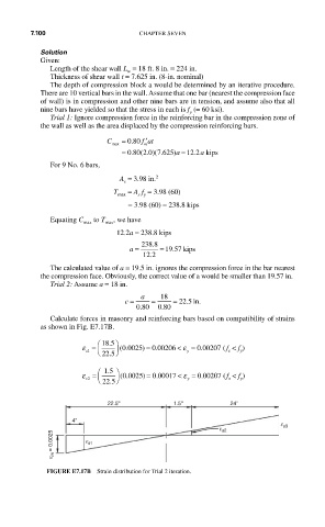
             Calculate forces in masonry and reinforcing bars based on compatibility of strains
           as shown in Fig. E7.17B.
                         ⎛  18 5 ⎞
                            .
                     ε = ⎜   ⎟ (.   )  0 00206 <  ε = .    f
                               0 0025 = .
                                                 0 002007 (   < f )
                      s1  ⎝ 22 5 ⎠             y         s  y
                            .
                          15 ⎞
                         ⎛ .
                     ε = ⎜   ⎟ (.   )  0 00017 <  ε = .
                                                 0 002077 ( f  < f )
                               0 0025 = .
                           22 5 ⎠
                      s2  ⎝                    y         s  y
                            .
                           22.5''          1.5''         24''
                   4''
                                                                      e s3
                                                       e s2
              e m = 0.0025  e s1
              FIGURE E7.17B  Strain distribution for Trial 2 iteration.
   533   534   535   536   537   538   539   540   541   542   543