
Page 145 - Design of Simple and Robust Process Plants
P. 145
130 Chapter 4 Process Synthesis and Design Optimization
For reactor systems, simple designs have an integration with the energy structure.
When we look at the examples presented under reactor simplification we immedi-
ately notice the integration with energy. The example in Figure 4.6 reflects a loop
reactor replaced by a boiling reactor where six exchangers are replaced by one
exchanger. Any form of energy recovery in this concept is more likely to be per-
formed economically.
When we compare the replacement of three cooled CSTRs with one adiabatic
CSTR and an adiabatic plug flow (Figure 4.7), the improvements in reactor config-
uration are striking (low cost at close to identical selectivity and conversion). The
improvements in energy recovery are also significant, as all the reaction heat is now
available in the effluent for utilization in the separation section.
The development in nitration technology show a similar effect when cooled
CSTRs are replaced by an adiabatic plug flow reactor, while heat utilization is
directly applied for separation, Figure 4.8.
The reverse flow reactor (Figure 4.9) includes cross-exchange between reactor
inlet and outlet in the reactor vessel, with utilization of reaction heat. More examples
are known, but it is these examples that clearly illustrate the usefulness of clever
integration of energy and reactor.
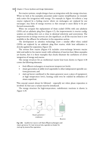
The energy structure for an exothermal reactor heat train shown in Figure 4.38
covers the following elements:
. feed effluent exchangers at maximum temperature levels;
. steam generation at utility level exportable to other independent operable sec-
tions/processes; and
. start-up heater combined in the steam generator saves a piece of equipment;
at high temperature levels, heating could even be realized by utilization of
steam superheat.
This concept cannot always be followed ± especially not when phase separation is
involved. In that case a variant must be introduced.
The energy structure for high-temperature, endothermic reactions is shown in
Figure 4.39.
Steam
Steam generator /
condenser
Reactor
Fig. 4.38. Exothermal reactor with feed effluent exchangers and
steam generator for heat removal also operable as heater for
start-up by reverse flow operation.