
Page 159 - Design of Solar Thermal Power Plants
P. 159
144 3. GENERAL DESIGN OF A SOLAR THERMAL POWER PLANT
aperture (refer to Fig. 3.16); G r is the Grashof number; Nu is the
Nusselt number.
In case that the receiver is placed horizontally, q ¼ 0, the
respective Nusselt number is Nu 0 .
Nusselt numbers corresponding to other dip angles and the
respective ratios are:
Nu 2:47
¼ cos q (3.21)
Nu 0
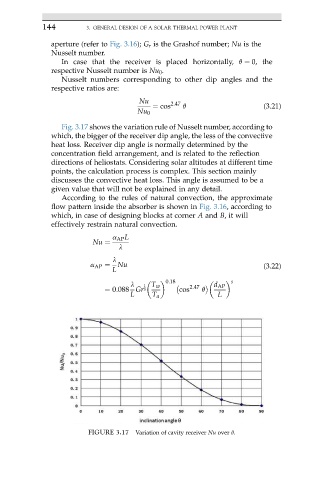
Fig. 3.17 shows the variation rule of Nusselt number, according to
which, the bigger of the receiver dip angle, the less of the convective
heat loss. Receiver dip angle is normally determined by the
concentration field arrangement, and is related to the reflection
directions of heliostats. Considering solar altitudes at different time
points, the calculation process is complex. This section mainly
discusses the convective heat loss. This angle is assumed to be a
given value that will not be explained in any detail.
According to the rules of natural convection, the approximate
flow pattern inside the absorber is shown in Fig. 3.16, according to
which, in case of designing blocks at corner A and B, it will
effectively restrain natural convection.
a AP L
Nu ¼
l
l
a AP ¼ Nu (3.22)
L
0:18 s
l 1 T w 2:47 d AP
¼ 0:088 Gr 3 cos q
L T a L
FIGURE 3.17 Variation of cavity receiver Nu over q.