
Page 158 - Design of Solar Thermal Power Plants
P. 158
3.2 HELIOSTAT FIELD EFFICIENCY ANALYSIS 143
After measuring the absorber surface temperature T w ,by
substituting Eq. (3.16) into Eq. (3.15), formula for calculating
radiation heat loss of receiver can be easily obtained.
4
ε w s T T 4 g A 1
w
P RAD ¼ (3.18)
A 2
1 ð1 ε w Þ 1
A 1
3. Convective heat loss P conv . Convective heat losses of receiver include
natural convective heat loss and forced convective heat loss. The
forced convective heat loss will not be explained in this section at
this moment, only the method for calculating natural convective
heat loss will be discussed. Driven by buoyance, natural convection
is related to the shape of the absorber, the installation dip of receiver
(Fig. 3.16), as well as the surface temperature of absorber and the
respective distribution. It is extremely difficult to achieve precise
conclusions only based on theoretical analysis. In this section, the
experimental formula Sieber Kraabel model is applied to calculate
the Nusselt number
0:18 8
1 T w 2:17 d AP
Nu ¼ 0:088Gr 2 ðcos qÞ (3.19)
T a L
0:982d AP
s ¼ 1:12 (3.20)
L
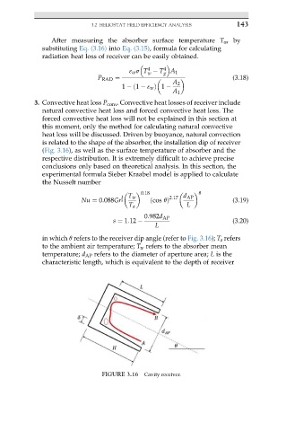
in which q refers to the receiver dip angle (refer to Fig. 3.16); T a refers
to the ambient air temperature; T w refers to the absorber mean
temperature; d AP refers to the diameter of aperture area; L is the
characteristic length, which is equivalent to the depth of receiver
FIGURE 3.16 Cavity receiver.