
Page 154 - Design of Solar Thermal Power Plants
P. 154
3.2 HELIOSTAT FIELD EFFICIENCY ANALYSIS 139
porous materials. Solar radiation is transmitted and absorbed within the
entire volume of absorber, which is frequently used together with the
system that uses heat-transfer fluid as the gas. The tubular receiver consists
of several pieces of tubes. Solar radiation will be absorbed on the surface of
the absorber tube; interior wall of the tube exchanges thermal energy with
the heat-transfer fluid flowing through the tube by the convection heat
transfer, the heat-transfer medium of which is liquid in most of the cases.
For a cavity receiver, the heat loss P LOSS can be calculated as follows [21]
(3.9)
P LOSS ¼ P REFCAV þ P RAD þ P CONV þ P COND
in which P REFCAV refers to the reflective radiation loss of the cavity
receiver; P RAD refers to the radiation heat loss from the surface of absorber
inside the cavity receiver to the outside through receiver aperture; P CONV
refers to the thermal convection from the surface of absorber to the
outside through receiver aperture; P COND refers to the conductive heat
loss from the surface of absorber to the outside heat loss.
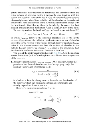
The area of the cavity receiver is shown in Fig. 3.11.A 1 is the aperture
2
area of the receiver (unit: m ) and A 2 is the area of inner absorbing surface
of the receiver.
1. Reflective radiation loss P REFCAV U marov (1983) equation, under the
premise of the thermal absorbent surface being a gray body, the
receiver’s equivalent absorptance a eff is
a w
a eff ¼ (3.10)
A 1
1 ð1 a w Þ 1
A 2
in which a w is the solar absorptance on the surface of the absorber of
the receiver, which can be measured through experiments and
usually depend on the temperature.
Receiver’s equivalent reflectance P COV is
r COV ¼ 1 a eff
a w
¼ 1 ¼ (3.11)
A 1
1 ð1 a w Þ 1
A 2
FIGURE 3.11 Schematic diagram of the area of the cavity receiver.