
Page 40 - Design of Solar Thermal Power Plants
P. 40
1.2 BRIEF INTRODUCTION TO SOLAR THERMAL POWER GENERATION 33
and spillage loss. Based on this, the concentration field layout
design must consider the causes for these losses and mitigate them
through a reasonable layout of concentrators to collect more solar
irradiation through the receivers.
a. Specular loss. Based on the need for concentrating efficiency,
specular reflectance on the reflective surface of the concentrator
is normally high, about 0.93e0.94. However, as a heliostat is
exposed to atmospheric conditions while functioning,
environmental factors such as dust and humidity will contribute
to decreases in specular reflectance.
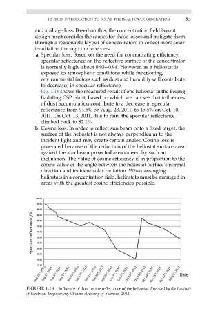
Fig. 1.18 shows the measured result of one heliostat in the Beijing
Badaling CSP plant, based on which we can see that influences
of dust accumulation contribute to a decrease in specular
reflectance from 94.6% on Aug. 23, 2011, to 45.5% on Oct. 10,
2011. On Oct. 13, 2011, due to rain, the specular reflectance
climbed back to 82.1%.
b. Cosine loss. In order to reflect sun beam onto a fixed target, the
surface of the heliostat is not always perpendicular to the
incident light and may create certain angles. Cosine loss is
generated because of the reduction of the heliostat surface area
against the sun beam projected area caused by such an
inclination. The value of cosine efficiency is in proportion to the
cosine value of the angle between the heliostat surface’s normal
direction and incident solar radiation. When arranging
heliostats in a concentration field, heliostats must be arranged in
areas with the greatest cosine efficiencies possible.
FIGURE 1.18 Influence of dust on the reflectance of the heliostat. Provided by the Institute
of Electrical Engineering, Chinese Academy of Sciences, 2012.