
Page 42 - Design of Solar Thermal Power Plants
P. 42
1.2 BRIEF INTRODUCTION TO SOLAR THERMAL POWER GENERATION 35
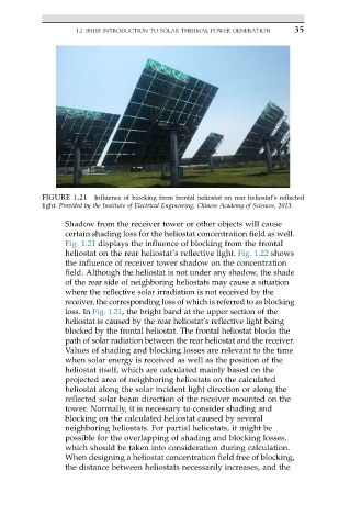
FIGURE 1.21 Influence of blocking from frontal heliostat on rear heliostat’s reflected
light. Provided by the Institute of Electrical Engineering, Chinese Academy of Sciences, 2013.
Shadow from the receiver tower or other objects will cause
certain shading loss for the heliostat concentration field as well.
Fig. 1.21 displays the influence of blocking from the frontal
heliostat on the rear heliostat’s reflective light. Fig. 1.22 shows
the influence of receiver tower shadow on the concentration
field. Although the heliostat is not under any shadow, the shade
of the rear side of neighboring heliostats may cause a situation
where the reflective solar irradiation is not received by the
receiver, the corresponding loss of which is referred to as blocking
loss. In Fig. 1.21, the bright band at the upper section of the
heliostat is caused by the rear heliostat’s reflective light being
blocked by the frontal heliostat. The frontal heliostat blocks the
path of solar radiation between the rear heliostat and the receiver.
Values of shading and blocking losses are relevant to the time
when solar energy is received as well as the position of the
heliostat itself, which are calculated mainly based on the
projected area of neighboring heliostats on the calculated
heliostat along the solar incident light direction or along the
reflected solar beam direction of the receiver mounted on the
tower. Normally, it is necessary to consider shading and
blocking on the calculated heliostat caused by several
neighboring heliostats. For partial heliostats, it might be
possible for the overlapping of shading and blocking losses,
which should be taken into consideration during calculation.
When designing a heliostat concentration field free of blocking,
the distance between heliostats necessarily increases, and the