
Page 45 - Design of Solar Thermal Power Plants
P. 45
38 1. INTRODUCTION
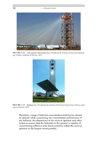
FIGURE 1.24 Atmospheric attenuation loss. Provided by the Institute of Electrical Engineer-
ing, Chinese Academy of Sciences, 2011.
FIGURE 1.25 Spillage loss. Provided by the Institute of Electrical Engineering, Chinese Acad-
emy of Sciences, 2013.
Therefore, a range of heliostat concentration field layouts should
be defined while considering the concentration performance of
the heliostat, the dimensions of the receiver aperture and other
factors to ensure that the heliostat on the ground is capable of
concentrating reflective solar beam radiation within the receiver
aperture to the largest extent possible.