
Page 46 - Design of Solar Thermal Power Plants
P. 46
1.2 BRIEF INTRODUCTION TO SOLAR THERMAL POWER GENERATION 39
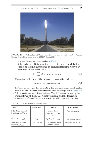
FIGURE 1.26 Spillage loss of Gemasolar solar tower power plant owned by Torresol
Energy, Spain. Picture provided by SENER, Spain, 2018.
Various losses are calculated in Table 1.5.
Solar radiation obtained on the receiver in the end shall be the
sum of all the energy projected by the heliostat on the receiver in
the entire concentration field:
X
h h
h h
E ¼ IAh cos ref S&B att int (1.1)
The optical efficiency of the heliostat concentration field is:
h field ¼ h cos ref S&B att int (1.2)
h h
h h
Features of software for calculating the annual mean optical perfor-
mance of the heliostat concentration field are compared in Table 1.6.
19. Mirror surface errors of concentrator. This is the error caused by the
inconsistency of the actual reflective surface and the theoretical
reflective surface of the concentrator, including canting position
TABLE 1.5 Calculation of Various Losses
Factor Calculation Factor Calculation
Solar direct normal I Atmospheric Ih cos h ref h S&B h att
2
irradiance/(W/m ) attenuation loss
(h att )
Cosine loss (h cos ) Ih cos Spillage loss (h int ) Ih cos h ref h S&B h att h int
Shadow and shade Ih cos h ref h S&B Concentration field IAh cos h ref h S&B h att h int
losses (h ref ,h S&B ) aperture area (A)