
Page 44 - Design of Solar Thermal Power Plants
P. 44
1.2 BRIEF INTRODUCTION TO SOLAR THERMAL POWER GENERATION 37
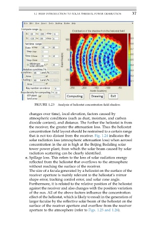
FIGURE 1.23 Analysis of heliostat concentration field shadow.
changes over time), local elevation, factors caused by
atmospheric conditions (such as dust, moisture, and carbon
dioxide content), and distance. The further the heliostat is from
the receiver, the greater the attenuation loss. Thus the heliostat
concentration field layout should be restrained to a certain range
that is not too distant from the receiver. Fig. 1.24 indicates the
solar radiation loss (atmospheric attenuation loss) when aerosol
concentration in the air is high at the Beijing Badaling solar
tower power plant, from which the solar beam caused by solar
radiation scattering can be clearly identified.
e. Spillage loss. This refers to the loss of solar radiation energy
reflected from the heliostat that overflows to the atmosphere
without reaching the surface of the receiver.
The size of a facula generated by a heliostat on the surface of the
receiver aperture is mainly relevant to the heliostat’s mirror
shape error, tracking control error, and solar cone angle.
Furthermore, it is related to the relative position of the heliostat
against the receiver and also changes with the position variation
of the sun. All of the above factors influence the concentration
effect of the heliostat, which is likely to result in the generation of
larger faculae by the reflective solar beam of the heliostat on the
surface of the receiver aperture and overflow from the receiver
aperture to the atmosphere (refer to Figs. 1.25 and 1.26).