
Page 41 - Design of Solar Thermal Power Plants
P. 41
34 1. INTRODUCTION
FIGURE 1.19 Cosine loss of heliostat.
Fig. 1.19 shows the ratio of solar irradiation received on certain
areas of the surface to the maximum received solar irradiation,
which is equivalent to the cosine value of the angle between the
incident beam and the normal direction of the receiving surface.
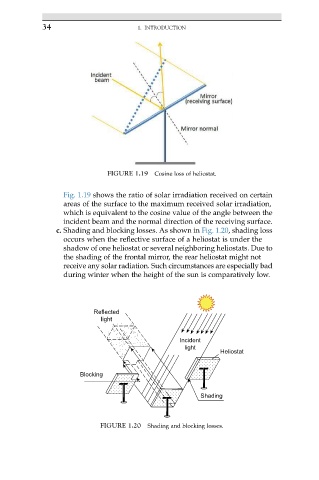
c. Shading and blocking losses. As shown in Fig. 1.20, shading loss
occurs when the reflective surface of a heliostat is under the
shadow of one heliostat or several neighboring heliostats. Due to
the shading of the frontal mirror, the rear heliostat might not
receive any solar radiation. Such circumstances are especially bad
during winter when the height of the sun is comparatively low.
Reflected
light
Incident
light
Heliostat
Blocking
Shading
FIGURE 1.20 Shading and blocking losses.