
Page 49 - Design of Solar Thermal Power Plants
P. 49
42 1. INTRODUCTION
1.2.3.2 Thermodynamic Terms
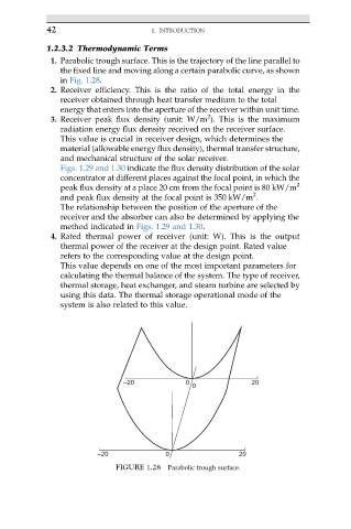
1. Parabolic trough surface. This is the trajectory of the line parallel to
the fixed line and moving along a certain parabolic curve, as shown
in Fig. 1.28.
2. Receiver efficiency. This is the ratio of the total energy in the
receiver obtained through heat transfer medium to the total
energy that enters into the aperture of the receiver within unit time.
2
3. Receiver peak flux density (unit: W/m ). This is the maximum
radiation energy flux density received on the receiver surface.
This value is crucial in receiver design, which determines the
material (allowable energy flux density), thermal transfer structure,
and mechanical structure of the solar receiver.
Figs. 1.29 and 1.30 indicate the flux density distribution of the solar
concentrator at different places against the focal point, in which the
peak flux density at a place 20 cm from the focal point is 80 kW/m 2
2
and peak flux density at the focal point is 350 kW/m .
The relationship between the position of the aperture of the
receiver and the absorber can also be determined by applying the
method indicated in Figs. 1.29 and 1.30.
4. Rated thermal power of receiver (unit: W). This is the output
thermal power of the receiver at the design point. Rated value
refers to the corresponding value at the design point.
This value depends on one of the most important parameters for
calculating the thermal balance of the system. The type of receiver,
thermal storage, heat exchanger, and steam turbine are selected by
using this data. The thermal storage operational mode of the
system is also related to this value.
–20 0 20
0
–20 0 20
FIGURE 1.28 Parabolic trough surface.