
Page 224 - Digital Analysis of Remotely Sensed Imagery
P. 224
188 Cha pte r F i v e
can be extended to rectify a block of overlapping images or photographs
via tie points (TPs) that are distinctive landmarks in the overlapping
portion of stereoscopic images/photographs. These TPs should possess
the same characteristics as GCPs except that they should be located
at the corners and midway near the border of the overlapping zone. With
the use of these TPs, the number of GCPs on individual images can be
drastically reduced, even to zero. As with the standard image rectifica-
tion, the ground coordinates are modeled as functions of the image
coordinates using the principle of least-squares adjustment (Zhou and
Jezek, 2004). With modification this method can be used to orthorectify
SPOT images obtained through along-track scanning. In this case the
equations apply to lines of an image instead of a frame of an image.
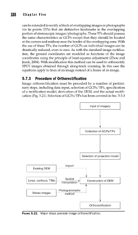
5.7.3 Procedure of Orthorectification
Image orthorectification must be preceded by a number of prelimi-
nary steps, including data input, selection of GCPs/TPs, specification
of a rectification model, derivation of the DEM, and the actual rectifi-
cation (Fig. 5.21). Selection of GCPs/TPs has been covered in Sec. 5.5.3
Input of imagery
Collection of GCPs/TPs
Selection of projection model
Import
Existing DEM
Spatial
Lines, contours, TINs Construction of DEM
Interpolation
Photogrammetric
Stereo images method
Orthorectification
FIGURE 5.21 Major steps precede image orthorectifi cation.