
Page 226 - Digital Analysis of Remotely Sensed Imagery
P. 226
190 Cha pte r F i v e
Satellite
Viewing direction
Surface relief
Geoid
P 0 P 1
Geoid height (+)
Geoid height (–)
Ellipsoid
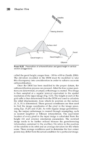
FIGURE 5.22 Precondition of orthorectifi cation and geoid height in vertical
section (exaggerated).
called the geoid height, ranges from −100 to +100 m (Smith, 2006).
The elevation recorded in the DEM must be modified to take
this discrepancy into consideration in order to achieve accurate
orthorectification.
Once the DEM has been modified to the proper datum, the
orthorectification process can proceed. After the four corner posi-
tions are determined, an empty orthoimage is created. This image
is then sampled at a regular interval equivalent to the spatial
resolution of the input image (Fig. 5.23). The height at each of the
grid cells is then determined from the DEM and used to calculate
the relief displacement, from which its position on the surface
(E, N, H) is determined. These ground coordinates are then used
to find the image coordinates of the pixel in the image space,
using Eqs. (5.25) and (5.26). As with regular image georeferenc-
ing, the output orthoimage is created through resampling, such
as nearest neighbor or bilinear interpolation. The equivalent
location of every pixel in the input image is calculated from the
height (H) and exterior orientation parameters. The rectified
image needs to be further refined because the georeferencing
information contained in the ancillary file refers to the position
of the satellite in its orbit and an average elevation for the whole
scene. These average conditions used to determine the four corner
points may differ from the actual condition for a particular image.