
Page 230 - Digital Analysis of Remotely Sensed Imagery
P. 230
194 Cha pte r F i v e
Northing Easting Height v e j
Average 0.006 0.014 −0.005 −0.450 0.000 0.000
error
Standard 0.121 0.061 0.224 19.581 16.783 32.146
error
Source: Kinn 2002.
TABLE 5.5 Difference between Camera Exterior Orientation Provided by GPS/IMU
and Aerotriangulation (Position in Meters and Angles in Arc Seconds)
Their accuracy can be improved by reconciling the errors in these sys-
tems through the Kalman filter that provides error estimates for the
camera’s position and altitude. These estimates can be used to modify
altitude and position to achieve higher accuracy. Consequently, posi-
tions can be accurate to a decimeter, and angles to 20 arc seconds in roll
and pitch with an adjustment of approximately 20 arc seconds, and to
30 arc seconds in heading (Table 5.5). Residual orientation errors are
due most likely to misalignment of the inertial platform during flight.
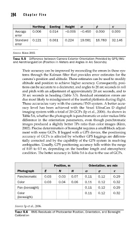
These accuracies vary with the camera/INS system. A better accu-
racy level has been achieved with the Vexel UltraCan D digital
imaging system with a total of 20 GCPs (Ip et al., 2006). As shown in
Table 5.6, whether the photograph is panchromatic or color makes little
difference in the orientation parameters, even though panchromatic
images produced a slightly better TPs ratio than color images (Kinn,
2002). Precise determination of boresight requires a small block adjust-
ment with some GCPs. If logged with a GPS device, the positioning
accuracy of GCPs is affected by whether GPS loggings are differen-
tially corrected and by the capability of the GPS system in resolving
ambiguities. Usually, GPS positioning accuracy falls within the range
of 0.05 to 0.5 m, depending on the baseline length and atmospheric
condition. The better accuracy in Table 5.6 is due to the use of GCPs.
Position, m Orientation, arc min
Photograph E N H v i j
Panchromatic 0.03 0.03 0.07 0.11 0.12 0.29
Color 0.03 0.04 0.06 0.11 0.12 0.32
Pan (boresight) 0.11 0.12 0.29
Color 0.11 0.12 0.32
(boresight)
Source: Ip et al., 2006.
TABLE 5.6 RMS Residuals of Photocenter Position, Orientation, and Boresight
Calibration