Page 283 - Distributed model predictive control for plant-wide systems
P. 283

Hot-Rolled Strip Laminar Cooling Process with Distributed Predictive Control  257


                                                             Reference Cooling curve
                                                             Cooling curve


                        900
                      Temperature (°C)  800


                        700

                        600
                         0                                                    0
                              2
                                                                      10
                                   4
                                        6
                                                             20
                                             8
                                                 10  30         Strip point
                                    Time (s)
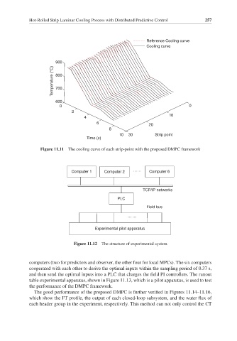
                 Figure 11.11  The cooling curve of each strip-point with the proposed DMPC framework


                              Computer 1   Computer 2  ……     Computer 6


                                                           TCP/IP networks
                                                 PLC
                                                             Field bus
                                                     … …


                                        Experimental pilot apparatus

                               Figure 11.12  The structure of experimental system


             computers (two for predictors and observer, the other four for local MPCs). The six computers
             cooperated with each other to derive the optimal inputs within the sampling period of 0.37 s,
             and then send the optimal inputs into a PLC that charges the field PI controllers. The runout
             table experimental apparatus, shown in Figure 11.13, which is a pilot apparatus, is used to test
             the performance of the DMPC framework.
               The good performance of the proposed DMPC is further verified in Figures 11.14–11.16,
             which show the FT profile, the output of each closed-loop subsystem, and the water flux of
             each header group in the experiment, respectively. This method can not only control the CT
   278   279   280   281   282   283   284   285   286   287   288