
Page 306 - Distributed model predictive control for plant-wide systems
P. 306
280 Distributed Model Predictive Control for Plant-Wide Systems
Cooling load Cooling load Cooling load Cooling load
(High floors) (Middle floors) (Middle floors) (Lower floors)
Water cooling network
Large power Small power
Conventional Exchanger Conventional
refrigerator V3 refrigeratior
V2
V4
Ice storage tank
Dual Mode V1
Chiller
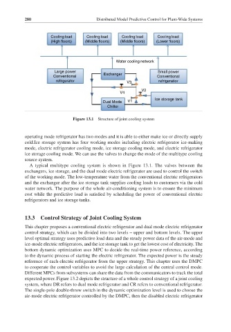
Figure 13.1 Structure of joint cooling system
operating mode refrigerator has two modes and it is able to either make ice or directly supply
cold.Ice storage system has four working modes including electric refrigerator ice-making
mode, electric refrigerator cooling mode, ice storage cooling mode, and electric refrigerator
ice storage cooling mode. We can use the valves to change the mode of the multitype cooling
source system.
A typical multitype cooling system is shown in Figure 13.1. The valves between the
exchangers, ice storage, and the dual mode electric refrigerator are used to control the switch
of the working mode. The low-temperature water from the conventional electric refrigerators
and the exchanger after the ice storage tank supplies cooling loads to customers via the cold
water network. The purpose of the whole air-conditioning system is to ensure the minimum
cost while the predictive load is satisfied by scheduling the power of conventional electric
refrigerators and ice storage tanks.
13.3 Control Strategy of Joint Cooling System
This chapter proposes a conventional electric refrigerator and dual mode electric refrigerator
control strategy, which can be divided into two levels – upper and bottom levels. The upper
level optimal strategy uses predictive load data and the steady power data of the air-mode and
ice-mode electric refrigerators, and the ice storage tank to get the lowest cost of electricity. The
bottom dynamic optimization uses MPC to decide the real-time power reference, according
to the dynamic process of starting the electric refrigerator. The expected power is the steady
reference of each electric refrigerator from the upper strategy. This chapter uses the DMPC
to cooperate the control variables to avoid the large calculation of the central control mode.
Different MPCs from subsystems can share the data from the communicators to track the total
expected power. Figure 13.2 depicts the structure of a whole control strategy of a joint cooling
system, where DR refers to dual mode refrigerator and CR refers to conventional refrigerator.
The single-pole double-throw switch in the dynamic optimization level is used to choose the
air-mode electric refrigerator controlled by the DMPC, then the disabled electric refrigerator