
Page 69 - Distributed model predictive control for plant-wide systems
P. 69
Control Structure of Distributed MPC 43
MPC
Communication
network
MPC MPC MPC MPC MPC
*
* y
u 1 * y 1 u 2 2 u 3 * y 3 u * m–1 y m–1 u y m
m
S *
S Na
S 1 S 2 S *
Plant-wide system S 3 S Na-1
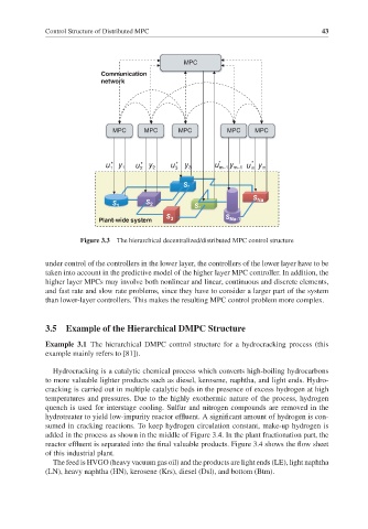
Figure 3.3 The hierarchical decentralized/distributed MPC control structure
under control of the controllers in the lower layer, the controllers of the lower layer have to be
taken into account in the predictive model of the higher layer MPC controller. In addition, the
higher layer MPCs may involve both nonlinear and linear, continuous and discrete elements,
and fast rate and slow rate problems, since they have to consider a larger part of the system
than lower-layer controllers. This makes the resulting MPC control problem more complex.
3.5 Example of the Hierarchical DMPC Structure
Example 3.1 The hierarchical DMPC control structure for a hydrocracking process (this
example mainly refers to [81]).
Hydrocracking is a catalytic chemical process which converts high-boiling hydrocarbons
to more valuable lighter products such as diesel, kerosene, naphtha, and light ends. Hydro-
cracking is carried out in multiple catalytic beds in the presence of excess hydrogen at high
temperatures and pressures. Due to the highly exothermic nature of the process, hydrogen
quench is used for interstage cooling. Sulfur and nitrogen compounds are removed in the
hydrotreater to yield low-impurity reactor effluent. A significant amount of hydrogen is con-
sumed in cracking reactions. To keep hydrogen circulation constant, make-up hydrogen is
added in the process as shown in the middle of Figure 3.4. In the plant fractionation part, the
reactor effluent is separated into the final valuable products. Figure 3.4 shows the flow sheet
of this industrial plant.
The feed is HVGO (heavy vacuum gas oil) and the products are light ends (LE), light naphtha
(LN), heavy naphtha (HN), kerosene (Krs), diesel (Dsl), and bottom (Btm).