
Page 542 - Dust Explosions in the Process Industries
P. 542
Assessment oflgnitability 509
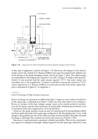
FILTER PAPER
PERSPEX CYLINDER
d
ONE-WAY VALVE,
I '.I-
LsoLENoiD VALVES
AND TIMING SYSTEM
COMPRESSED AIR RESERVOIR
Figure 7.34 Apparatus for determining the minimum ignition energy ofdust clouds.
in this type of apparatus is shown in Figure 7.35. However, the energies of the electric
sparks used in the original U.S. Bureau of Mines test were not satisfactorilydefined, due
to the design of the spark discharge circuit, shown in Figure 7.36(a). The spark energy
was generatedby dischargingthe capacitor C at a DC voltage V through a step-up trans-
former. It was assumed that the spark energy equaled l/2CV2, but some energy was
inevitably lost in the transfomer. A tentative correlation among the numerous '/zCV2
values reported by U.S. Bureau of Mines over the years and the real electric spark ener-
gies is indicated in Figure A. 1 in Appendix 1.
7.1 0.2.2
Direct Discharge of High-Voltage Capacitors
Direct discharge of' capacitors at sufficiently high voltages to ensure direct breakdown
of the spark gap, as illustrated in Figure 7.36(b), has also been used for test purposes.
However, because 'of the high voltage, energy losses in the switch needed to synchro-
nize the discharge with the dust cloud may be appreciable. Sophisticatedelements such
as thyratrons have been employed to solve this problem.
However,the spark and dust cloud can also be synchronizedby incorporatinga third,
auxiliary spark electrode in the spark gap configuration. By dischargingjust a very small
energy in the gap between one of the main electrodes and the auxiliaryelectrode, the main
discharge is initiated. This method was used with success by Franke (1978).
Mechanical synchronizationconstitutes a further possibility. Prior to the experiment,
the capacitor is charged to the high voltage required with the spark gap sufficiently long