
Page 544 - Dust Explosions in the Process Industries
P. 544
Assessment of lgnitability 5 7 1
SWITCH
(a) LOW-VOLTAGE CAPACITOR DISCHARGED TliROUGH TRANSFORMER
(ORIGINAL US. BUREAU OF MINES CIRCUIT)
SWITCH
(b) OIRECT DISCHARGE OF HIGH-VOLTAGE CAPACITOR
WITHOUT AND WITH INDUCTANCE
(c) [MI-DISCHARGE CIRCUIT
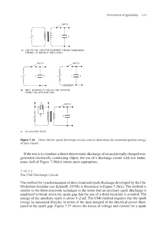
Figure 7.36 Three electric spark discharge circuits used to determine the minimum ignition energy
of dust clouds.
If the test is to simulate a direct electrostaticdischarge of an accidentally charged non-
grounded electrically conducting object, the use of a discharge circuit with low induc-
tance (left of Figure 7.36(b)) seems most appropriate.
7.1 0.2.3
The CMI Discharge Circuit
The method for synchronizationof dust cloud and spark discharge developed by the Chr.
Michelsen Institute (see Eckhoff, 1975b)is illustrated in Figure 7.36(c). The method is
similar to the three-electrode technique in the sense that an auxiliary spark discharge is
employed to break down the spark gap, but the use of a third electrode is avoided. The
energy of the auxiliary spark is about 1-2 mJ. The CMI method requires that the spark
energy be measured directly, in terms of the time integral of the electrical power dissi-
pated in the spark gap. Figure 7.37 shows the traces of voltage and current €or a spark