
Page 171 - Dynamic Loading and Design of Structures
P. 171
Page 147
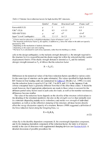
Table 4.5 Seismic force reduction factors for high ductility R/C structures.
Symbol Frame Structural wall Frame wall
EurocodeS(ULS) q 5 4–5 4.5–5
1
UBC (ULS) R 8.5 4.5–5.5 8.5
2
NZS 4203 (ULS) µ <6 3 <5 4 <5–6 4
4
Japan (Level 2 earthquake) I/D s 2.2–3.3 l.8–2.5 2.0–2.9
1
R factor must be reduced by a reliability/redundancy factor of between 1 and 1 .5.
2 The structural performance factor S also applies, in addition to µ, hence the values in the table are typically
p
increased by 50%.
3 Depending on the mechanism of inelastic deformation.
4
Depending on the aspect ratio and coupling.
5 The factor D is calculated for each storey separately, rather than the building as a whole.
s
cally to the design earthquake), to the inelastic strength demand (i.e. the strength required in
the structure for it to respond beyond the elastic range but within the selected ductility (and/or
displacement) limits). If the elastic strength demand is denoted as F and the inelastic
el
(design) strength demand as F , it follows that the reduction factor
d
(4.21)
Differences in the numerical values of the force reduction factors specified in various codes
for the same type of structure can be quite substantial. The values specified for high ductility
R/C frames in four leading codes are summarised in Table 4.5 (Booth et al., 1998); it is seen
that the reduction factor is equal to 8.5 in UBC, 5 in EC8, and ≤3.3 in the Japanese Code
(whose conceptual basis is generally different from that of the other three codes). It should be
noted, however, that if appropriate adjustments are made to these values to account for the
different partial safety factors used in each code (for loads, as well as for member resistances),
differences become smaller.
The value of the reduction factor depends on the ductility of the structure (which relates to
the detailing of the structural members), but also on the strength reserves that normally exist
in a structure (depending mainly on its redundancy and on the over strength of individual
members), as well as on the (effective) damping of the structure; all these factors directly
affect the energy dissipation capacity of a structure. Bertero (1989) suggested a definition of
the force reduction factor along the foregoing lines, i.e.
(4.22)
where Rµ is the ductility dependent component, Rs the overstrength dependent component,
and R the damping dependent component of the reduction factor; the latter is of interest
ξ
mainly in the case of structures with supplemental damping devices (see Section 4.4.4). A
detailed discussion of possible procedures for