
Page 40 - Dynamic Vision for Perception and Control of Motion
P. 40
24 2 Basic Relations: Image Sequences – “the World”
as the x-direction of a body-fixed coordinate system (x b, y b, z b) with its origin 0 b at
the projection S b of S t onto the ground plane.
To describe motion in an all-dominating field of gravity, the plane of reference
may contain both the gravity and the velocity vector with the origin at the center of
gravity of the moving object. The “horizontal” plane normal to the gravity vector
also has some advantages, especially for vehicle dynamics since no gravity com-
ponent affects motion in it.
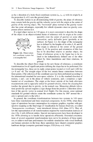
If a rigid object moves in 3-D space, it is most convenient to describe the shape
of the object in an object-oriented frame of reference with its origin at the center
(possibly even the center of gravity) or some other
B L / 2 L / 2 convenient, easily definable point (probably at its
surface). In Figure 2.2, the shape of the rectangular
H S t
box is defined by the lengths of its sides L, B, and H.
The origin is selected at the center of the ground
x b
S b =O b
y b
plane S b. If the position and orientation of this box
z b
has to be described relative to another object, the
Figure 2.2. Object-orien-
frame of reference given in the figure has to be re-
ted coordinate system for
lated to the independently defined one of the other
a rectangular box
object by three translations and three rotations, in
general.
To describe the object (box) shape in the new frame of reference, a coordinate
transformation for all significant points defining the shape has to be performed. For
the rectangular box, these are its eight corner points located at r L/2 and r B/2 for
z b= 0 and íH. The straight edges of the box remain linear connections between
these points. [The selection of the coordinate axes has been performed according to
the international standard for aero-space vehicles. X is in the standard direction of
motion, x and z are in the plane of vehicle symmetry, and y completes a right-
handed set of coordinates. The origin at the lower outside of the body alleviates
measurements and is especially suited for ground vehicles, where the encasing box
touches the ground due to gravity, in the normal case. Measuring altitude (eleva-
tion) positively upward requires a sign change from the positive z-direction (direc-
tion of the gravity vector in normal level flight). For this reason, some national
standards for ground vehicles rotate the coordinate system by 180° around the x-
axis (z upward and y to the left).]
In general, the coordinate transformations between two systems in 3-D space
have three translational and three rotational components. In the 1970s, when these
types of operations became commonplace in computer graphics, together with per-
spective mapping as the final stage of visualization for human observers, so-called
“homogeneous coordinates” were introduced [Roberts 1965, Blinn 1977]. They al-
low the representation of all transformations required by transformation matrices of
size 4 by 4 with different entries. Special microprocessors have been developed in
the 1970s allowing us to handle these operations efficiently. Extended concatena-
tions of several sequential transformations turn out to be products of these matri-
ces; to achieve real-time performance for realistic simulations with visual feedback
and human operators in the loop, these operations have shaped computer graphics
hardware design (computer generated images, CGI [Foley et al. 1990]).